Installing a Modular Sensor in OCI
This topic describes how to install a Modular Sensor in an Oracle Cloud Infrastructure environment. Refer to the following sections for details:
Use our example as a guideline, as you might be using a different software version.
About Modular Sensors
Sensors provide the data gathering foundation for Stellar Cyber's OpenXDR platform, gathering the right data with context. Modular sensors are purpose-built Stellar Cyber sensors that include both the host and the Stellar Cyber monitoring software. They are provided as both physical devices (Photon sensors) and virtual machine images for different target environments.
Previous releases provided a variety of different types of device sensors, including Network, Security, and Modular. Going forward, the only type of device sensor is Modular. You can use the Modular Sensor Profile to enable whatever sensor features you like, creating the same functionality provided by the different sensor types in previous releases.
A modular sensor lets you easily add the features you like to your sensor. This helps simplify your deployment and lets you manage the VM requirements for the sensors based on the modular features they use.
Modular Sensors always include log ingestion. From there, you can enable different features as part of your modular sensor profile:
-
Enable the Network Traffic feature to monitor the virtual environment, the physical environment if connected to the span port of a physical switch, or the LAN segment via a mirror port on a switch. The sensor monitors network and server response times and can identify applications.
The sensor converts that information to metadata and forwards it to the DP as Interflow. The DP can then provide security, DDoS, and breach attempt detections.
-
Enable the Sandbox and IDS features to improve your security posture:
- Sandbox lets you detect malware in files and network traffic through Stellar Cyber's integrated cloud service and also provides anti-virus services.
- IDS lets you detect intrusion attempts using both files and network traffic.
Keep in mind that VM resource requirements increase as you add more features to the Modular Sensor Profile. Refer to Modular Sensor Specifications for details on the resources required to run different combinations of features in a Modular Sensor Profile, as well as how to use the show module and show module request CLI commands to compare provisioned resources against those required to run specific feature combinations. Stellar Cyber only enables a Modular Sensor Profile on a sensor if the host VM's resources can support it.
Stellar Cyber does not support the installation of third-party software on its virtual or physical device sensors.
Site Preparation
Refer to Modular Sensor Specifications for details on the resources required to run different combinations of features in a Modular Sensor Profile. Provision your modular sensor according to the features that you plan on enabling.
You will also need to open firewall ports for the features you plan on enabling in the Modular Sensor Profile for this sensor.
Obtaining the Installation File
You can download the image for a modular sensor in OCI using the link below.
Installation links point to the most recent release. To download a different version, simply substitute the version you want for the version specified in the link.
-
Download the modular sensor image from the Stellar Cyber production server at the following URL:
https://acps.stellarcyber.ai/release/5.1.1/datasensor/aella-modular-ds-5.1.1.qcow2
Contact Stellar Cyber support (support@stellarcyber.ai) for login credentials and a one-time password (also known as a License Key).
Installing the Modular Sensor Image
This section describes how to install the Modular Sensor image in OCI:
-
Log in to Oracle Cloud Console at https://cloud.oracle.com/.
-
Click the main menu icon at the top left of the Oracle Cloud Console.

-
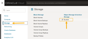
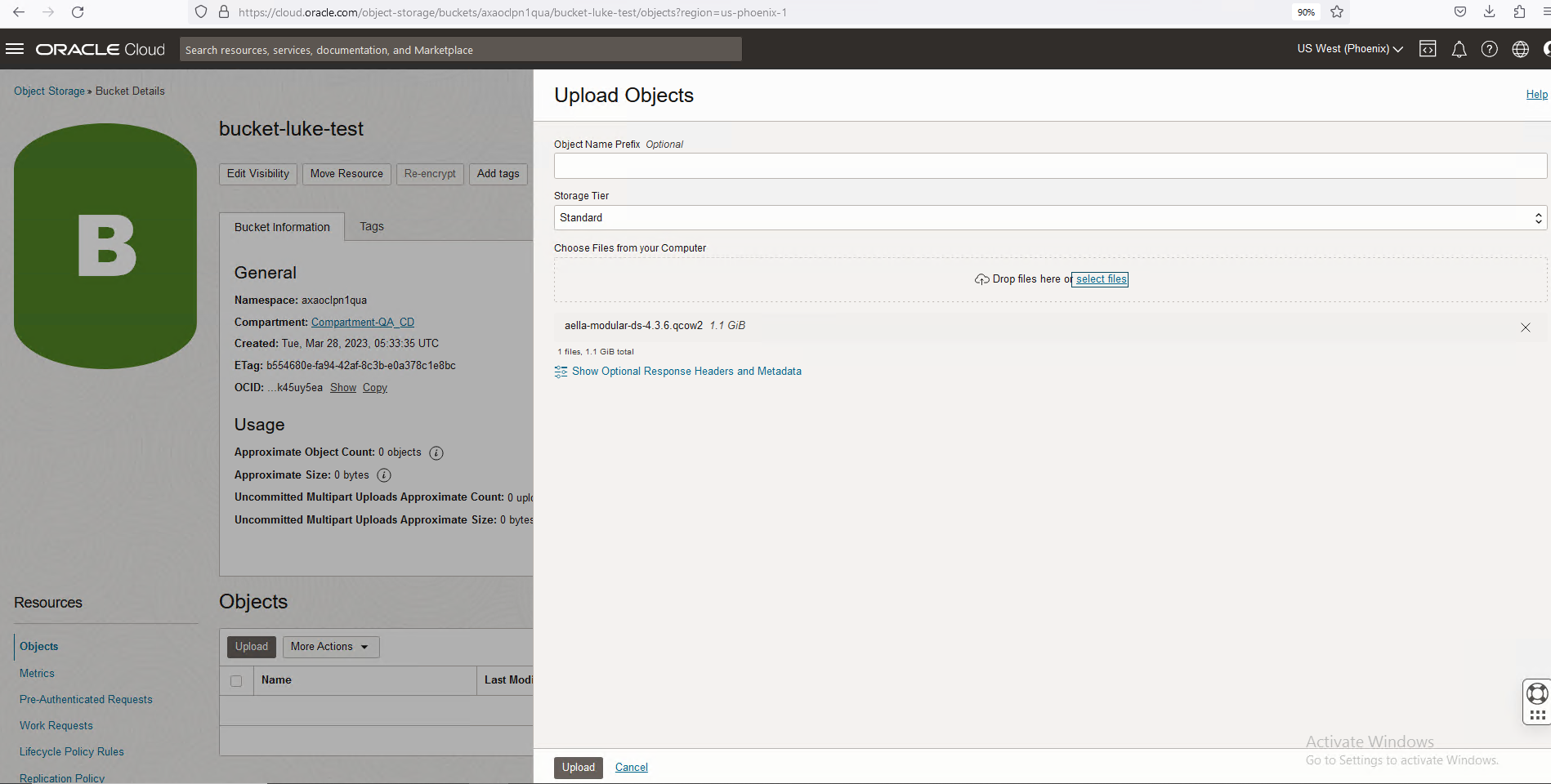
If you do not already have a bucket for the Modular Sensor, navigate to Storage | Buckets.
-
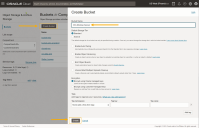
Click Create Bucket to add a new bucket. Select the Standard storage tier, supply a name, and click Create to add the bucket to your account.
-
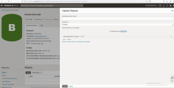
Click the entry for the bucket you just created. Then, use the Upload button to upload the aella-modular-ds-4.3.x.qcow2 image you received in Obtaining the Installation File. The Choose Files from your Computer field lets you either drag and drop the file or select the file in a standard Browse dialog box.
-
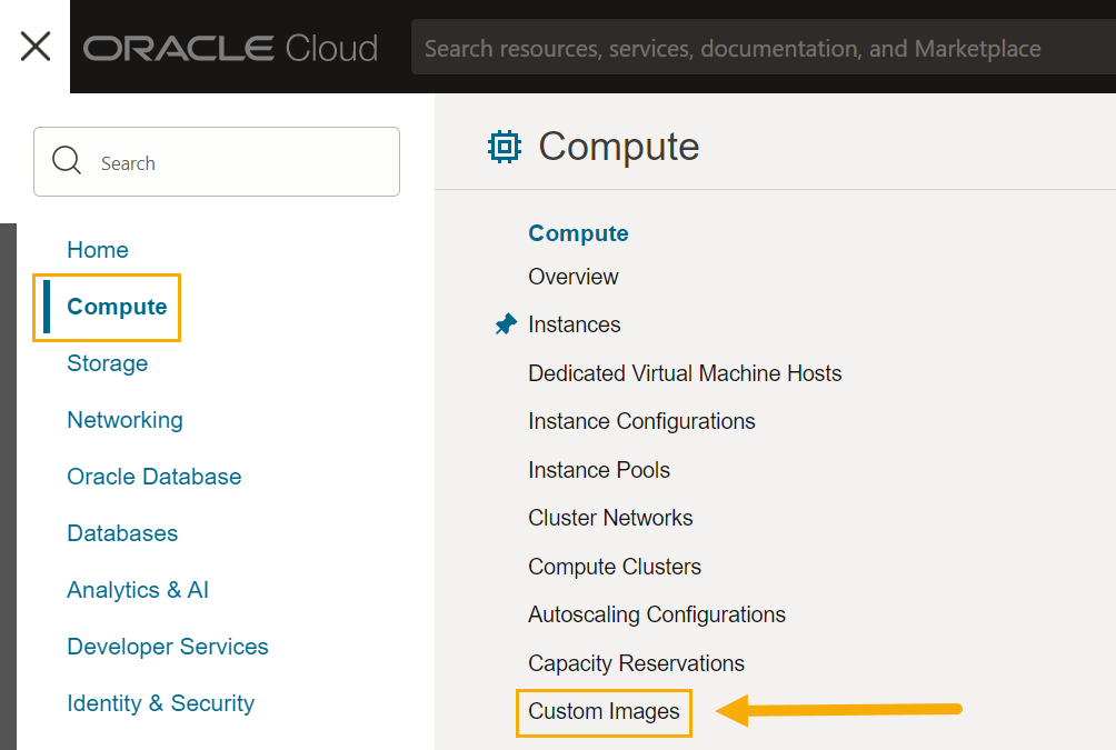
Click the main menu icon and navigate to Compute | Custom Images.

-
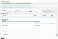
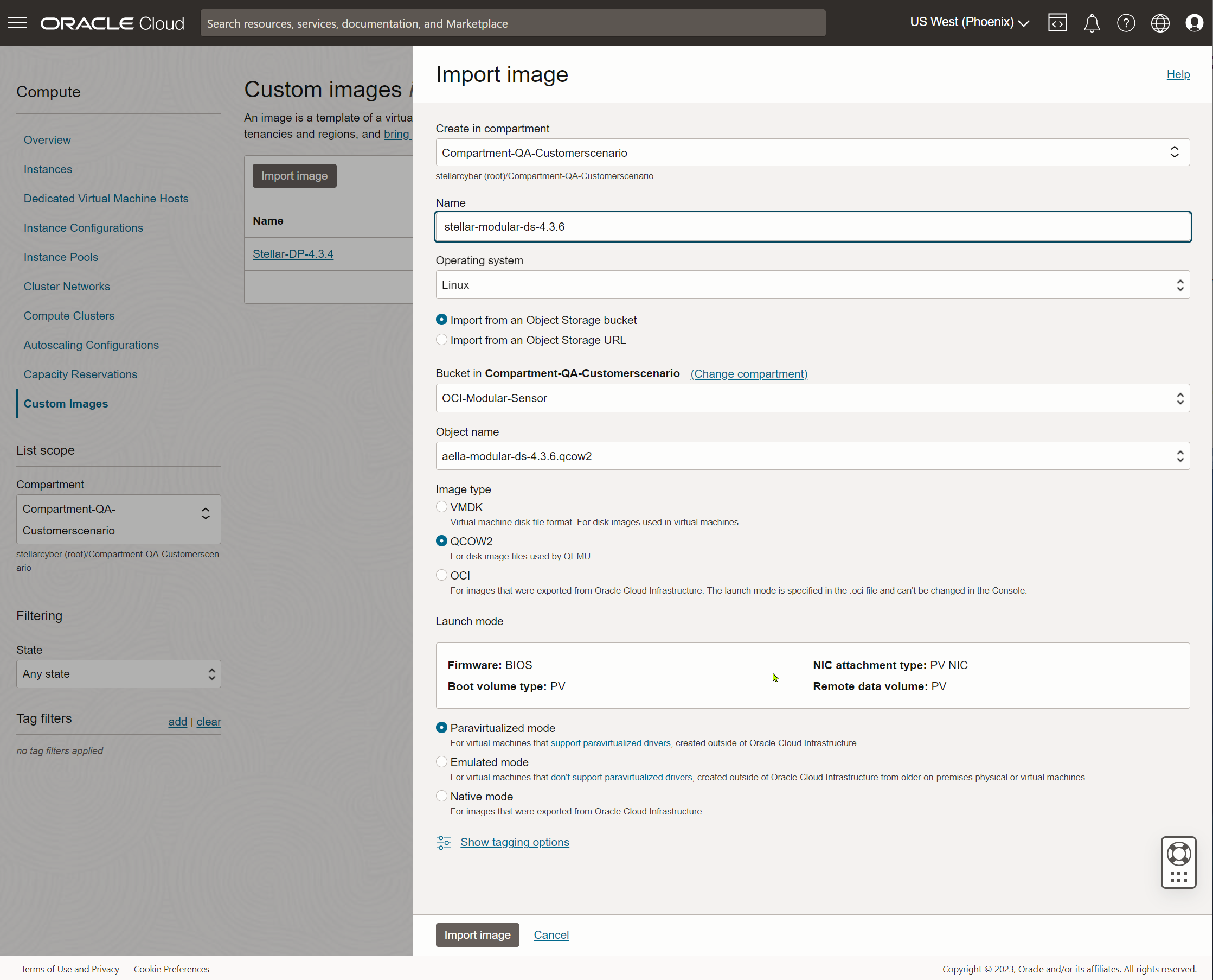
Click the Import image button and fill out the Import image dialog box as follows:
-
Supply a Name.
-
Use the Bucket field to select the bucket where you uploaded the image at the start of this procedure.
-
Use the Object name field to select the aella-modular-ds-5.1.1.qcow2 image.
-
Set the Operating system to Ubuntu.
-
Set the Image type field to QCOW2
-
Leave Launch mode set to Paravirtualized mode.
The figure below provides an example of the settings:

-
-
When you have finished configuring the settings in the Import image dialog box, click the Import image button to start the import process.
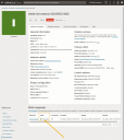
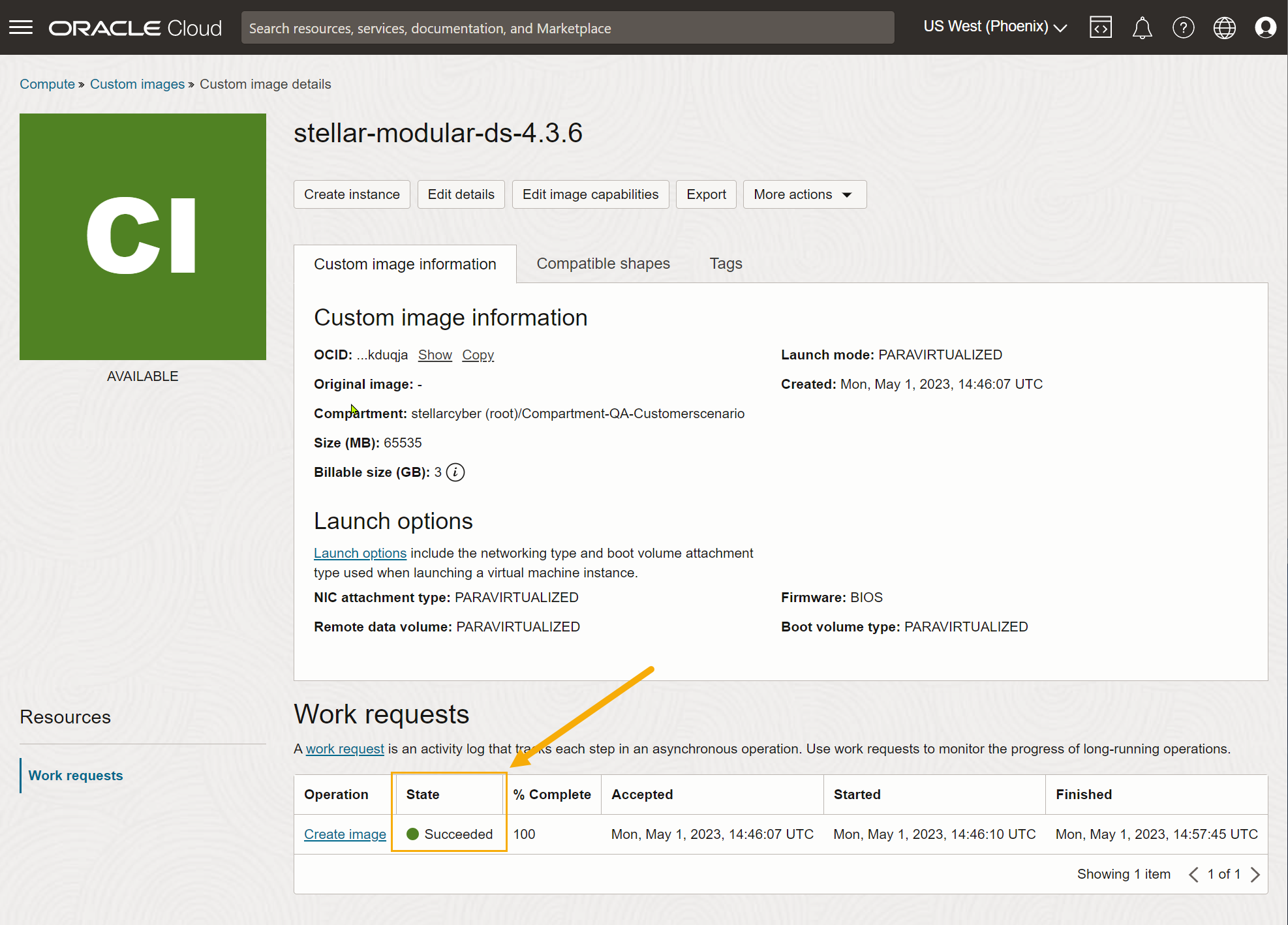
The Custom image details page appears for the image while it imports. When the image has finished importing, it appears with a value of Succeededin the State column, as shown below.
-
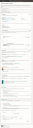
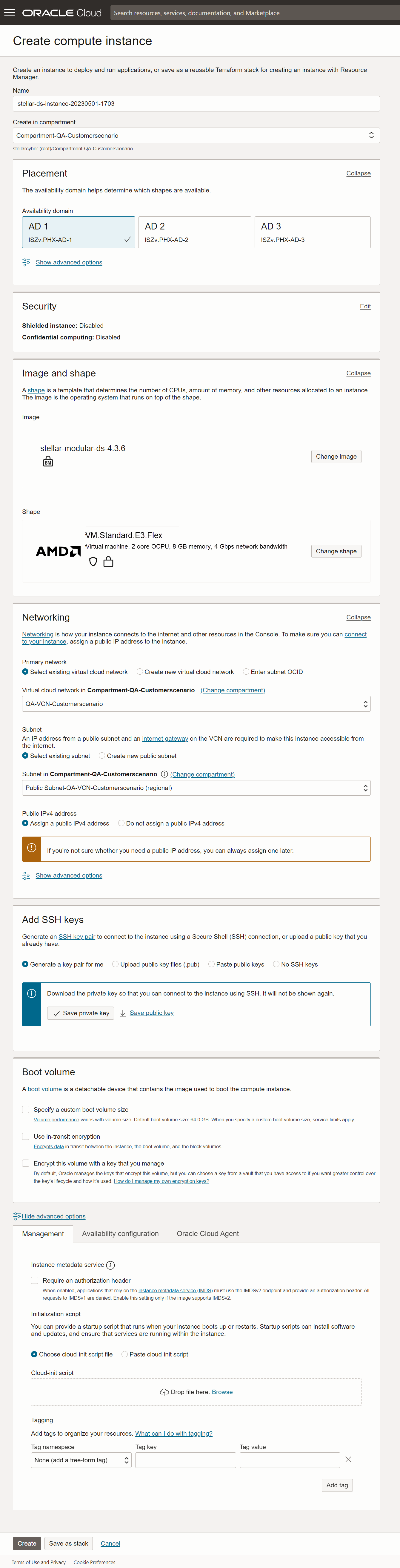
Once the image has finished importing, click the Create instance command to create a new instance based on the image. Set the options in the Create compute instance dialog box as follows:
-
Supply an easily identifiable Name for the new instance.
-
Choose the compartment and availability domain for the new instance. Make sure you choose the availability domain where you want to receive traffic.
-
Leave Image set to stellar-modular-ds-5.1.x.
-
The Shape field lets you select from VMs with a variety of different provisioning. Choose a shape that corresponds to the resources required by the features to be enabled in this sensor's Sensor Profile.
You can customize the CPUs and memory for many of the available shapes by clicking Change shape and adjusting as necessary. For example, we know we want to enable the Log Collector, Log Forward, and Network Traffic features, so we've chosen the VM.Standard.E4.Flex shape and adjusted its settings to the minimum values of 4 CPUs and 6 GB of memory.
-
Use the Networking options to select the Primary network and Subnet for the sensor's management interface.
-
In most cases, you'll want to Assign a public IPv4 address to the management interface. This lets you manage the sensor from a DP located outside the OCI public cloud.
-
Use the Add SSH keys options to decide how you want to connect to the sensor using SSH. We are letting OCI generate a key pair for us and saving the resulting private key locally.
-
You can leave the other options set to their defaults.
The figure below shows our settings so far.
-
-
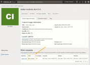
When you are satisfied with your settings, click Create to create the instance.
OCI begins to create the instance, tracking its progress in the Instance details | Work requests display. Once the State shown in the Work requests table shows Succeeded, as illustrated in the example below, you are ready to add a second VNIC to be used as a monitoring interface. See below.


Connecting the Sensor to the Stellar Cyber Platform
To connect the sensor to the Stellar Cyber Platform:
- Log in to your new sensor. The default username/password is aella/changeme. You are immediately prompted to change the password.
-
Change the password.
After you change the password, your session closes automatically. When you log back in with your new credentials, the prompt changes to DataSensor>.
-
Set the host name. The host name is displayed in Stellar Cyber and should be unique for each sensor:
set hostname <new hostname> -
If necessary, set the proxy HTTP server:
set proxy http://<proxy IP address:port>Note: The CLI prevents you from entering non-printable characters as part of the username or password for the proxy, as well as the proxy itself.
-
Optionally assign the tenant (if you skip this, the sensor is assigned to Root Tenant):
set tenant_id <Tenant ID from Stellar Cyber> -
Use the
set cmcommand to specify the IP address to reach the management interface of the Data Processor. For a DP cluster, this is the IP address of the DL-master's management interface. For a single DP deployment, this is simply the DP's management IP address. You can specify either an IP address or a hostname. For example:set cm 192.168.44.10or:
set cm example.company.comIf you specify a hostname rather than an IP address, the system attempts to verify the hostname with the DNS server. If the DNS server is not reachable, the system reports the error and lets you either proceed with the configured hostname or quit. This way, you can specify a hostname for the
set cmdestination in an offline environment without access to a DNS server. - Verify with the
show cmcommand. You should see the IP address of the DP listed as the CM Controller and the Status should be Established. -
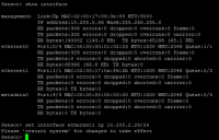
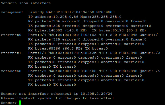
When you added a second VNIC to the sensor VM, you recorded the IP address that OCI automatically assigned to it. Now, you need to assign that IP address within the sensor CLI. Use the following command:
Sensor > set interface ethernet1 ip <ip address assigned by OCI>For example:
-
Use the
show timecommand to view the time zone.During installation, the timezone for sensors are automatically set to UTC+0. Since the logs for some security products may only include the local time without a timezone, Stellar Cyber recommends that you set the sensor timezone to the same timezone as your security product.
-
Use the
restart systemcommand to apply your changes.
Authorize the Sensor
You must authorize the sensor when it appears in the network.
You can authorize multiple sensors at a time. So if you're installing multiple sensors, install them all, then authorize them all at once.
