Installing a Modular Sensor in VMware
![]() Learn more at Stellar Cyber Academy.
Learn more at Stellar Cyber Academy.
The following links take you to courses on the Stellar Cyber Academy technical training portal where you can learn more about this topic by watching the suggested lessons.
Get introduced to installing and configuring a Stellar Cyber Modular Sensor on VMware ESXi. Learn about log forwarding, network traffic features, and the role of the sensor in collecting and analyzing telemetry for enhanced security operations.
Explore the high-level placement and capabilities of Modular Sensors within the Stellar Cyber Platform. Review key features, including network traffic capture, sandboxing, IDS, and firewall communication requirements for seamless deployment.
Watch a demo of configuring Modular Sensor features like log forwarding and network traffic. See steps for configuring Modular Sensor profiles to manage network flow and optimize security data collection.
Set up the ESXi environment for Modular Sensors, including creating port groups and enabling promiscuous mode. Learn how to configure network interfaces for management and traffic monitoring.
Follow a demonstration on configuring ESXi settings for Modular Sensors, covering network switches, port groups, and adding network adapters to facilitate traffic capture in the Stellar Cyber Platform.
Learn CLI commands to configure network settings, hostnames, and DNS for Modular Sensors. Understand how to establish connectivity to the Stellar Cyber Platform for seamless data forwarding.
Watch a demo on using CLI commands to configure Modular Sensors. See steps for setting IP addresses, gateway, DNS, and binding the sensor to the Stellar Cyber Platform.
Authorize the Modular Sensor in the Stellar Cyber UI, ensuring secure communication. Learn to monitor status indicators, confirm sensor health, and validate integration with the Stellar Cyber Platform.
See a demonstration of the Modular Sensor authorization process in the Stellar Cyber UI. Learn how to activate profiles, enable log forwarding, and view status indicators to confirm authorization.
Validate the Modular Sensor setup by monitoring syslog traffic. Ensure that log data reaches the Modular Sensor and is correctly forwarded to the Stellar Cyber Platform for processing and analysis.
Follow a demonstration to verify syslog traffic between the Modular Sensor and Stellar Cyber Platform. Learn techniques for checking log counters and validating data flow to the Stellar Cyber Platform.
The first time you access a link on the portal during a session, you must log in to access content.
This topic describes how to install a Modular Sensor in VMware.
About Modular Sensors
Sensors provide the data gathering foundation for Stellar Cyber's OpenXDR platform, gathering the right data with context. Modular sensors are purpose-built Stellar Cyber sensors that include both the host and the Stellar Cyber monitoring software. They are provided as both physical devices (Photon sensors) and virtual machine images for different target environments.
Previous releases provided a variety of different types of device sensors, including Network, Security, and Modular. Going forward, the only type of device sensor is Modular. You can use the Modular Sensor Profile to enable whatever sensor features you like, creating the same functionality provided by the different sensor types in previous releases.
A modular sensor lets you easily add the features you like to your sensor. This helps simplify your deployment and lets you manage the VM requirements for the sensors based on the modular features they use.
Modular Sensors always include log ingestion. From there, you can enable different features as part of your modular sensor profile:
-
Enable the Network Traffic feature to monitor the virtual environment, the physical environment if connected to the span port of a physical switch, or the LAN segment via a mirror port on a switch. The sensor monitors network and server response times and can identify applications.
The sensor converts that information to metadata and forwards it to the DP as Interflow. The DP can then provide security, DDoS, and breach attempt detections.
-
Enable the Sandbox and IDS features to improve your security posture:
- Sandbox lets you detect malware in files and network traffic through Stellar Cyber's integrated cloud service and also provides anti-virus services.
- IDS lets you detect intrusion attempts using both files and network traffic.
Keep in mind that VM resource requirements increase as you add more features to the Modular Sensor Profile. Refer to Modular Sensor Specifications for details on the resources required to run different combinations of features in a Modular Sensor Profile, as well as how to use the show module and show module request CLI commands to compare provisioned resources against those required to run specific feature combinations. Stellar Cyber only enables a Modular Sensor Profile on a sensor if the host VM's resources can support it.
Stellar Cyber does not support the installation of third-party software on its virtual or physical device sensors.
Site Preparation
Click to see the minimum system requirements for installing a modular sensor.
You will also need to:
- Open firewall ports for log ingestion.
- Open firewall ports for Network Traffic, Sandbox, and IDS features, as necessary.
One physical port on the system will be configured to receive network traffic to be analyzed. It must have promiscuous mode capability and be connected to an appropriate data source.
In addition, the system BIOS must have VT-d/IOMMU enabled.
Downloading Images
The virtual machine image for modular sensors in VMware can be downloaded from the Stellar Cyber production server at the link below.
Installation links point to the most recent release. To download a different version, simply substitute the version you want for the version specified in the link.
| Description | Version | URL |
|---|---|---|
| Modular Sensor | 5.3.0 | https://acps.stellarcyber.ai/release/5.4.0/datasensor/aella-modular-ds-5.4.0.ova |
Contact Stellar Cyber support (support@stellarcyber.ai) for login credentials.
Alternatively, you can use a curl command in a shell user environment to download the images. For example, the following command downloads a Version 5.3.0 Modular Sensor:
curl -k -u login:password https://acps.stellarcyber.ai/release/5.3.0/datasensor/aella-modular-ds-5.3.0.ova -o aella-modular-ds-5.3.0.ovaSupported ESXi Versions
Sensor installation is supported on the following ESXi versions:
- 8.0
- 7.0
- 6.7
Installation Steps
Once the prerequisites have been met, use the following procedure to install the sensor:
Use our example as a guideline, as you might be using a different software version.
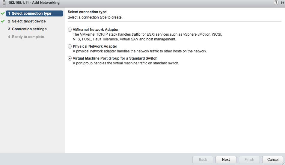
Create a new virtual switch with port mirroring capabilities. Start with the add-networking wizard function and select the Virtual Machine Port Group option as shown in the following image.
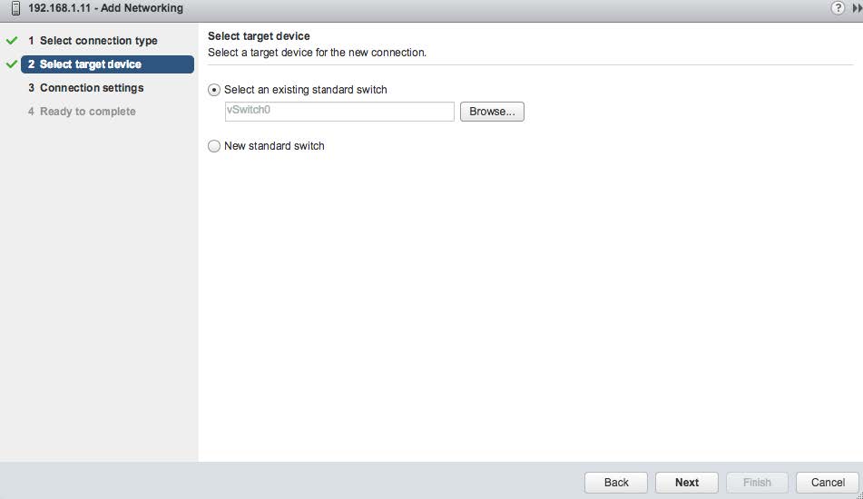
You can add the port to an existing switch or create a new switch. The following image shows the attachment being made to an existing switch named vSwitch0.
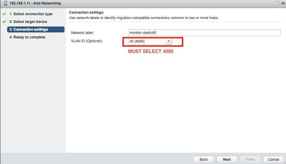
Create a network label with the VLAN ID of 4095. This is shown in the following image.
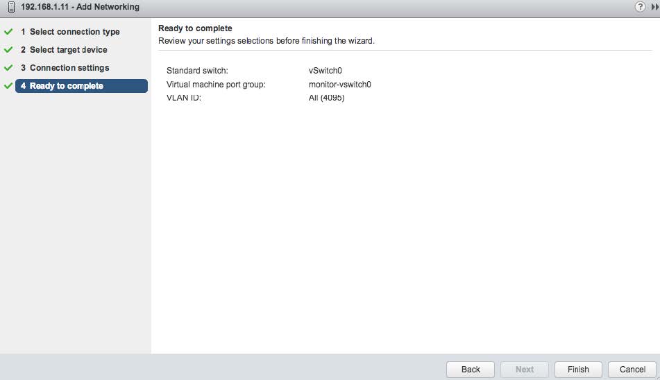
At this point the settings should be complete. Select the "FINISH" button as shown below.
When completed, the resulting switch can be seen in the Networking section of the vCenter Navigator as shown in the following image. Select the network connection as shown in "STEP 1" and then the Edit button shown as "STEP 2".
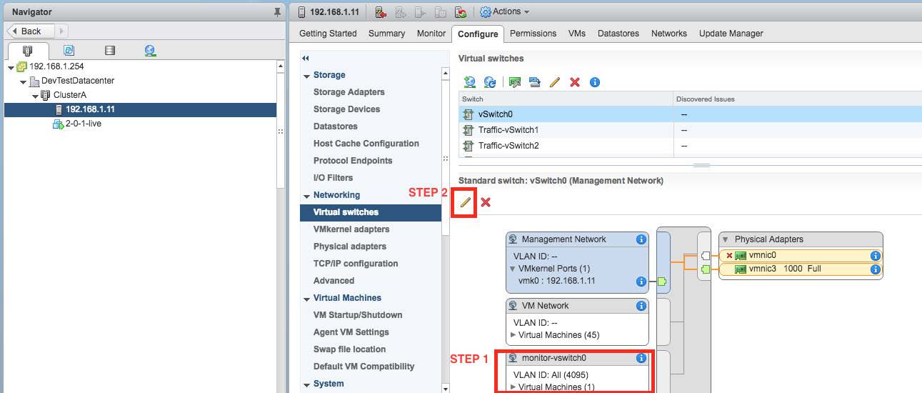
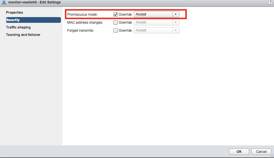
Select the "Security" panel option and enable Promiscuous Mode by selecting the appropriate Override and Accept controls as shown in the following image.
You can repeat the above steps as necessary to monitor additional ports.
The next steps create the VM. Select the option to deploy a new OVF template wizard and use the Local file option, as shown below.
The Stellar Cyber distribution provides an OVA file, which is a format that includes the requested OVF file as a component.

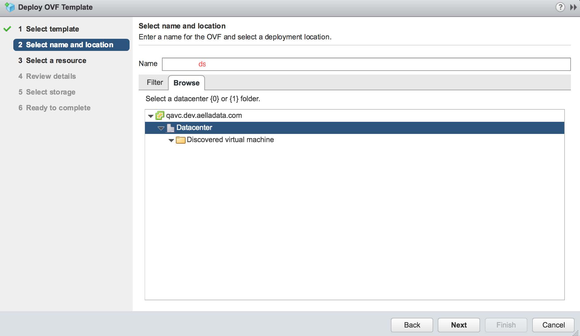
On the next screen provide the VM a name and select the appropriate data center where it will be deployed, as shown below:
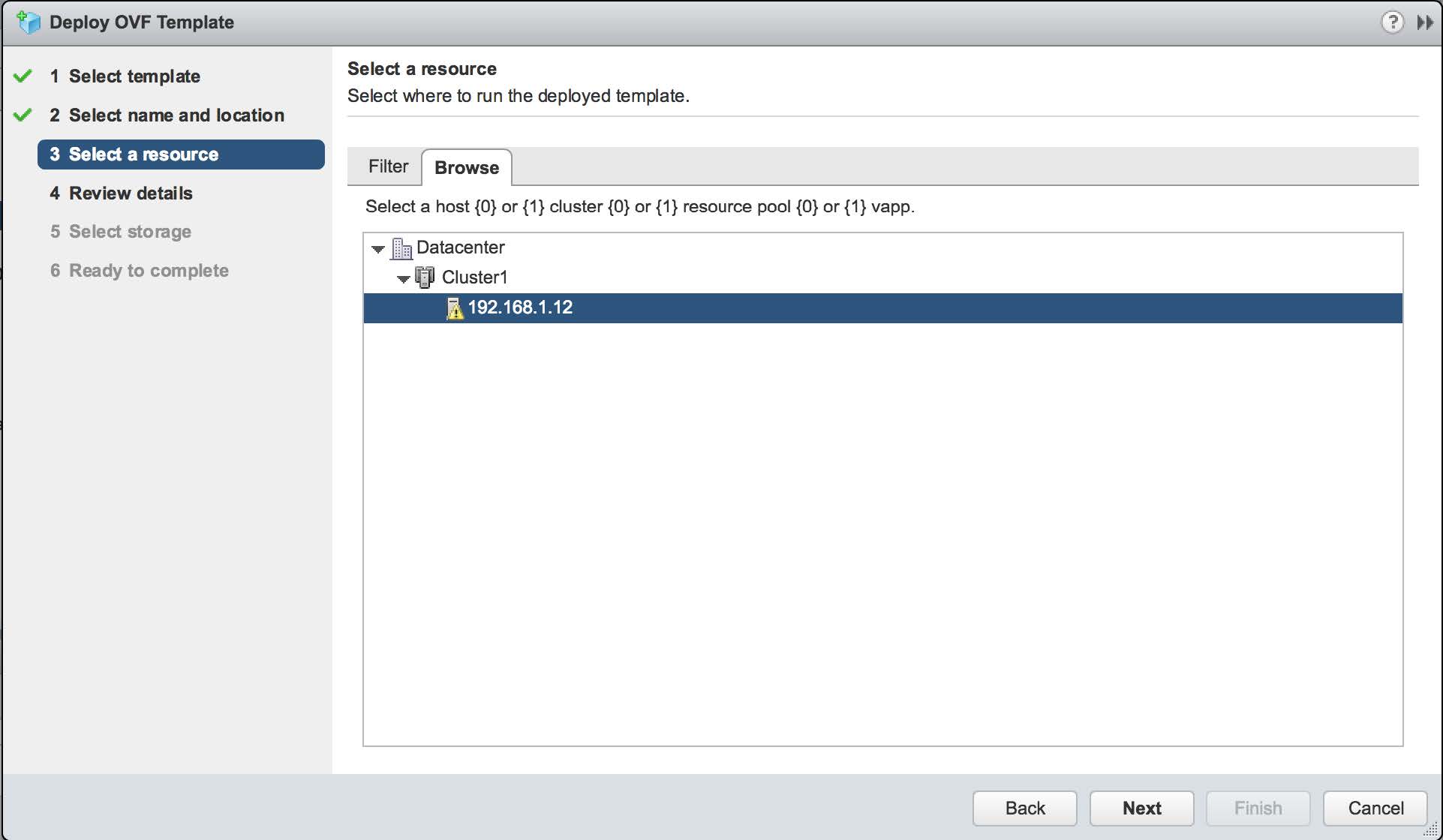
Within the data center, there may be more than one resource that can run the VM. Select the one which hosts the mirror port. A simple configuration is shown in the following image:
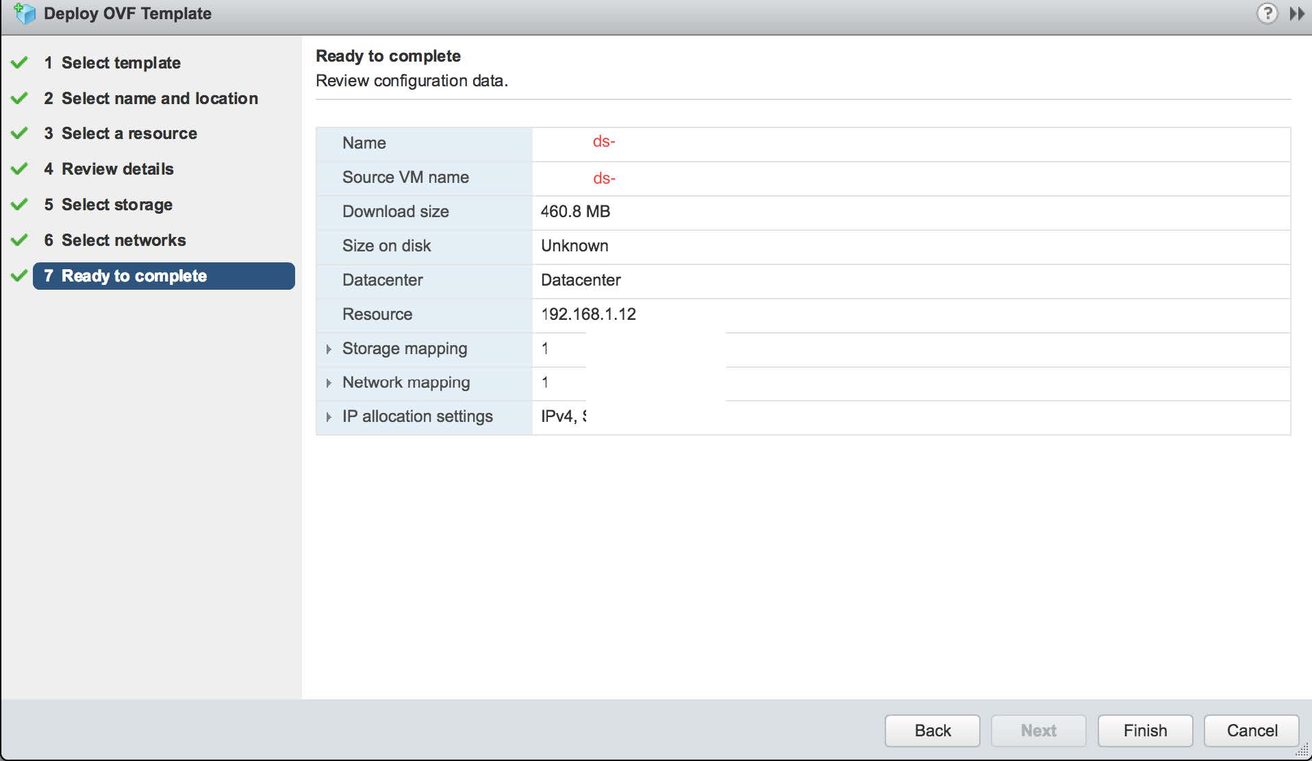
Once the selections are made, the summary page appears as follows. If the settings are correct, click the Finish button shown in the following image:
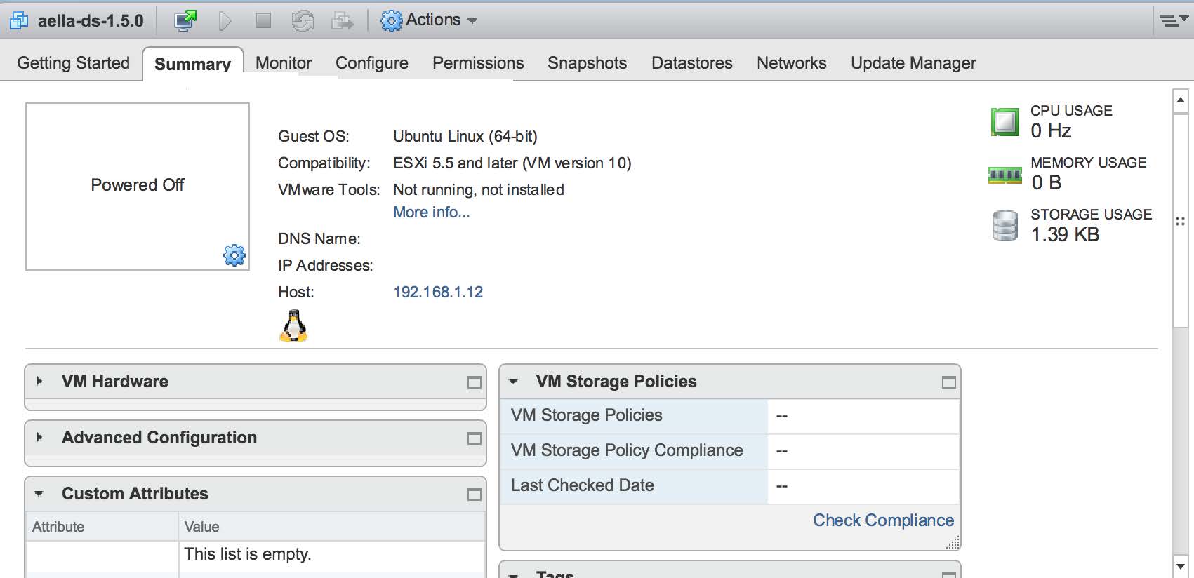
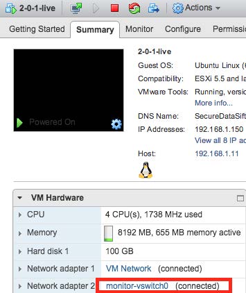
The VM is loaded into the hypervisor management and can then be seen in the vCenter summary page. An example of this is shown in the following image:
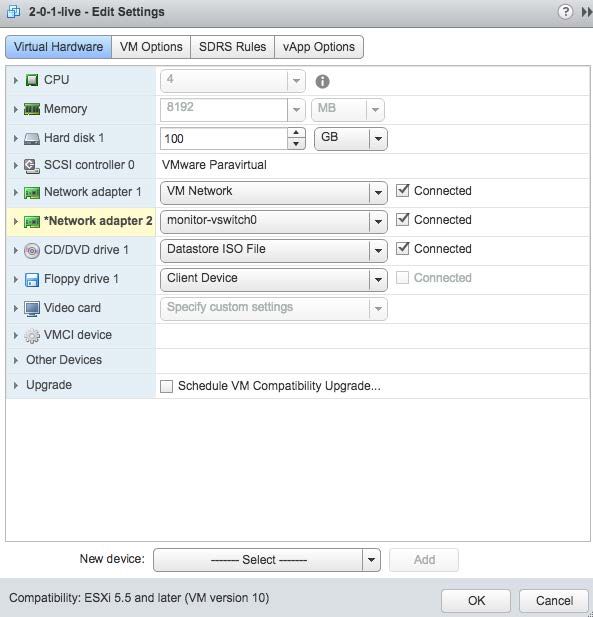
Expand the Virtual Hardware sub-page. The Management channel used by the sensor is implemented over "Network Adapter 1" which needs to be connected. Select it as shown in the following image:
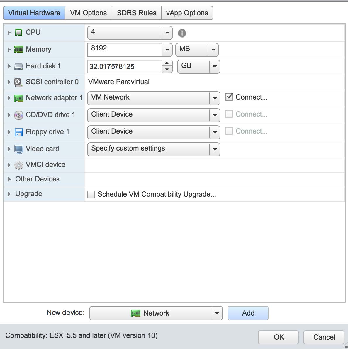
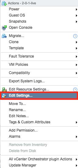
Select the "Edit Settings" menu item to add a second adapter. This is the network interface that will be used to monitor traffic on the virtual switch we created in prior steps. This is shown in the next two images. Note that you can only add a network adapter to the VM while it is powered off:
At this point the Sensor is installed and can be started. An example of this is shown in the following image:
Connecting the Sensor to the Stellar Cyber Platform
To connect to the DP:
- Log in to your new sensor. The default username/password is aella/changeme. You are immediately prompted to change the password.
-
Change the password.
After you change the password, your session closes automatically. When you log back in with your new credentials, the prompt changes to DataSensor>.
-
Set IP parameters for the management port. You can use either a static IP address or a DHCP server, if available.
Stellar Cyber recommends using a static IP address for ease of troubleshooting.
The commands are as follows:
Configuration Type
Commands
Static IP Substitute your own IP parameters for those shown in bold.
set interface management ip 192.168.14.100/255.255.255.0set interface management gateway 192.168.14.1set interface management dns 8.8.8.8DHCP set interface management ip dhcp -
Verify the IP settings with the
show interfacescommand. -
Set the host name. The host name is displayed in Stellar Cyber and should be unique for each sensor:
set hostname <new hostname> -
If necessary, set the proxy HTTP server:
set proxy http://<proxy IP address:port>Note: The CLI prevents you from entering non-printable characters as part of the username or password for the proxy, as well as the proxy itself.
-
If this sensor is associated with a specific Tenant, use the
set tenant_id <Tenant ID>command to specify the name of that tenant. For example:set tenant_id MyTenant -
Use the
set cmcommand to specify the IP address to reach the management interface of the Stellar Cyber Platform. For a cluster, this is the IP address of the DL-master's management interface. For a single DP deployment, this is simply the Stellar Cyber Platform's management IP address. You can specify either an IP address or a hostname. For example:set cm 192.168.44.10or:
set cm example.company.comIf you specify a hostname rather than an IP address, the system attempts to verify the hostname with the DNS server. If the DNS server is not reachable, the system reports the error and lets you either proceed with the configured hostname or quit. This way, you can specify a hostname for the
set cmdestination in an offline environment without access to a DNS server. - Verify your settings with the
show cmcommand. You should see the IP address of the Stellar Cyber Platform listed as the CM Controller and the Status should be Established. - Log out with the
quitcommand.
The sensor automatically contacts the Stellar Cyber Platform to register itself.
Configure NTP and Set the Timezone
Stellar Cyber strongly recommends that configure NTP and set the timezone for the sensor.
Refer to Best Practices for NTP and Timezones for details.
Authorize the Sensor
You must authorize the sensor when it appears in the network.
You can authorize multiple sensors at a time. So if you're installing multiple sensors, install them all, then authorize them all at once.
Enabling SSSE3 for the Modular Sensor VM
The Modular Sensor VM must have SSSE3 enabled for its processors in order to operate correctly. In most cases, SSSE3 will already be enabled. However, if you encounter issues with packet collection or Interflow data generation, you can use the instructions below to ensure that SSSE3 is enabled.
Sensors installed on Linux hosts must have SSSE3 enabled for their processors in order to operate correctly. This is true for Modular Sensors and Linux Server Sensors, as well as legacy Network and Security Sensors.
SSSE3 is typically supported/enabled for most vCPUs, but may not be for certain legacy AMD vCPUs. See below for instructions on enabling SSSE3.
To enable SSSE3 for a virtual machine:
-
Start the virtual shell (virsh)
-
Type the following command to edit the virtual machine's settings:
edit <virtual_machine_name> -
Locate the <cpu> section. It should appear similar to the following:
Copy<cpu mode='custom' match='exact' check='partial'>
<model fallback='allow'>SandyBridge</model>
......
</cpu> -
Add the following line to the <cpu> section:
<feature policy='require' name='ssse3'/>When you are done, the <cpu> section should appear similar to the following:
Copy<cpu mode='custom' match='exact' check='partial'>
<model fallback='allow'>SandyBridge</model>
<feature policy='require' name='ssse3'/>
...........
</cpu> -
Save changes to the virtual machine and exist virsh.
-
Run the following command:
virsh define /etc/libvirt/qemu/<virtual_machine_name>.xmlEach virtual machine has a configuration .xml file. Typically, these files are stored under /etc/libvirt/qemu, but the location may be different for your system.
-
Stop and start the virtual machine in virsh.
