Installing a Modular Sensor in OCI
This topic describes how to install a Modular Sensor in an Oracle Cloud Infrastructure environment. Refer to the following sections for details:
Use our example as a guideline, as you might be using a different software version.
Stellar Cyber does not support the installation of third-party software on its virtual or physical device sensors.
About Modular Sensors
Sensors provide the data gathering foundation for Stellar Cyber's OpenXDR platform, gathering the right data with context. Modular sensors are purpose-built Stellar Cyber sensors that include both the host and the Stellar Cyber monitoring software. They are provided as both physical devices (Photon sensors) and virtual machine images for different target environments.
Previous releases provided a variety of different types of device sensors, including Network, Security, and Modular. Going forward, the only type of device sensor is Modular. You can use the Modular Sensor Profile to enable whatever sensor features you like, creating the same functionality provided by the different sensor types in previous releases.
A modular sensor lets you easily add the features you like to your sensor. This helps simplify your deployment and lets you manage the VM requirements for the sensors based on the modular features they use.
Modular Sensors always include log ingestion. From there, you can enable different features as part of your modular sensor profile:
-
Enable the Network Traffic feature to monitor the virtual environment, the physical environment if connected to the span port of a physical switch, or the LAN segment via a mirror port on a switch. The sensor monitors network and server response times and can identify applications.
The sensor converts that information to metadata and forwards it to the DP as Interflow. The DP can then provide security, DDoS, and breach attempt detections.
-
Enable the Sandbox and IDS features to improve your security posture:
- Sandbox lets you detect malware in files and network traffic through Stellar Cyber's integrated cloud service and also provides anti-virus services.
- IDS lets you detect intrusion attempts using both files and network traffic.
Keep in mind that VM resource requirements increase as you add more features to the Modular Sensor Profile. Refer to Modular Sensor Specifications for details on the resources required to run different combinations of features in a Modular Sensor Profile, as well as how to use the show module and show module request CLI commands to compare provisioned resources against those required to run specific feature combinations. Stellar Cyber only enables a Modular Sensor Profile on a sensor if the host VM's resources can support it.
Site Preparation
Refer to Modular Sensor Specifications for details on the resources required to run different combinations of features in a Modular Sensor Profile. Provision your modular sensor according to the features that you plan on enabling.
You will also need to open firewall ports for the features you plan on enabling in the Modular Sensor Profile for this sensor.
This topic also describes how to configure a VTAP in OCI to direct data to a load balancer connected to a Modular Sensor's management port.
Obtaining the Installation File
You can download the image for a modular sensor in OCI using the link below.
Installation links point to the most recent release. To download a different version, simply substitute the version you want for the version specified in the link.
-
Download the modular sensor image from the Stellar Cyber production server at the following URL:
https://acps.stellarcyber.ai/release/5.4.0/datasensor/aella-modular-ds-5.4.0.qcow2
Contact Stellar Cyber support (support@stellarcyber.ai) for login credentials and a one-time password (also known as a License Key).
Installing the Modular Sensor Image
This section describes how to install the Modular Sensor image in OCI:
-
Log in to Oracle Cloud Console at https://cloud.oracle.com/.
-
Click the main menu icon at the top left of the Oracle Cloud Console.

-
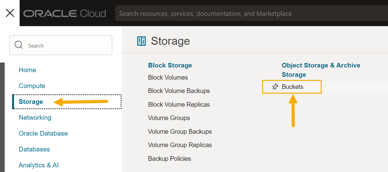
If you do not already have a bucket for the Modular Sensor, navigate to Storage | Buckets.
-
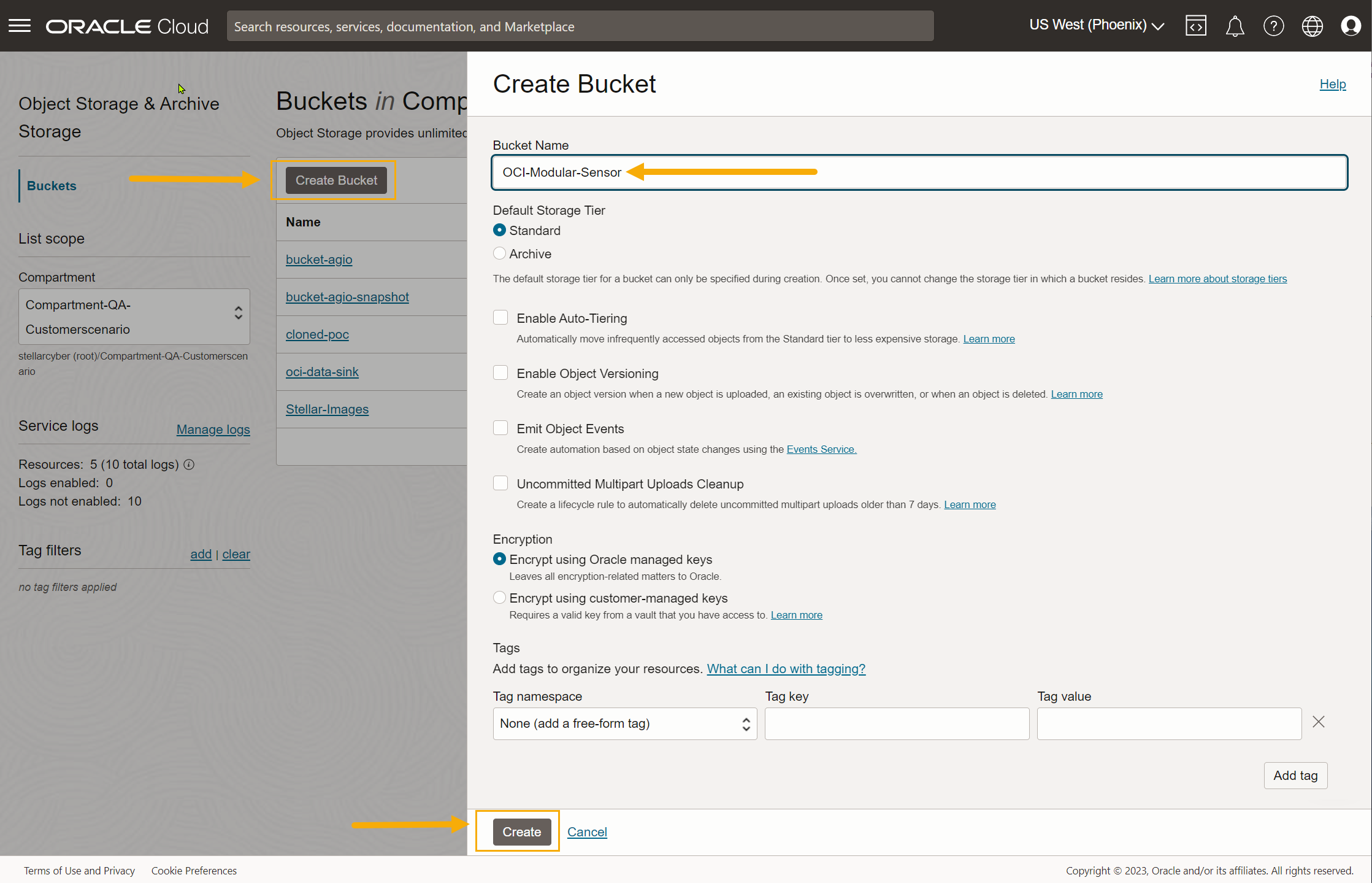
Click Create Bucket to add a new bucket. Select the Standard storage tier, supply a name, and click Create to add the bucket to your account.
-
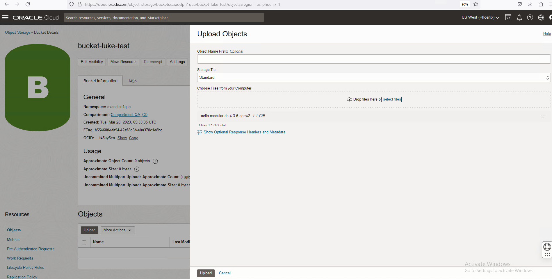
Click the entry for the bucket you just created. Then, use the Upload button to upload the aella-modular-ds-5.x.x.qcow2 image you received in Obtaining the Installation File. The Choose Files from your Computer field lets you either drag and drop the file or select the file in a standard Browse dialog box.
-
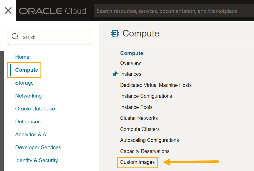
Click the main menu icon and navigate to Compute | Custom Images.
-
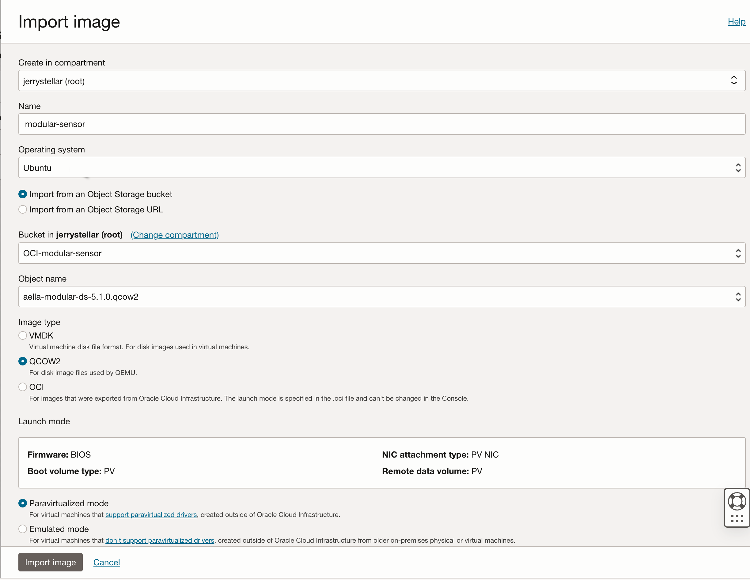
Click the Import image button and fill out the Import image dialog box as follows:
-
Supply a Name.
-
Use the Bucket field to select the bucket where you uploaded the image at the start of this procedure.
-
Use the Object name field to select the aella-modular-ds-5.x.x.qcow2 image.
-
Set the Operating system to Ubuntu.
-
Set the Image type field to QCOW2
-
Leave Launch mode set to Paravirtualized mode.
The figure below provides an example of the settings:
-
-
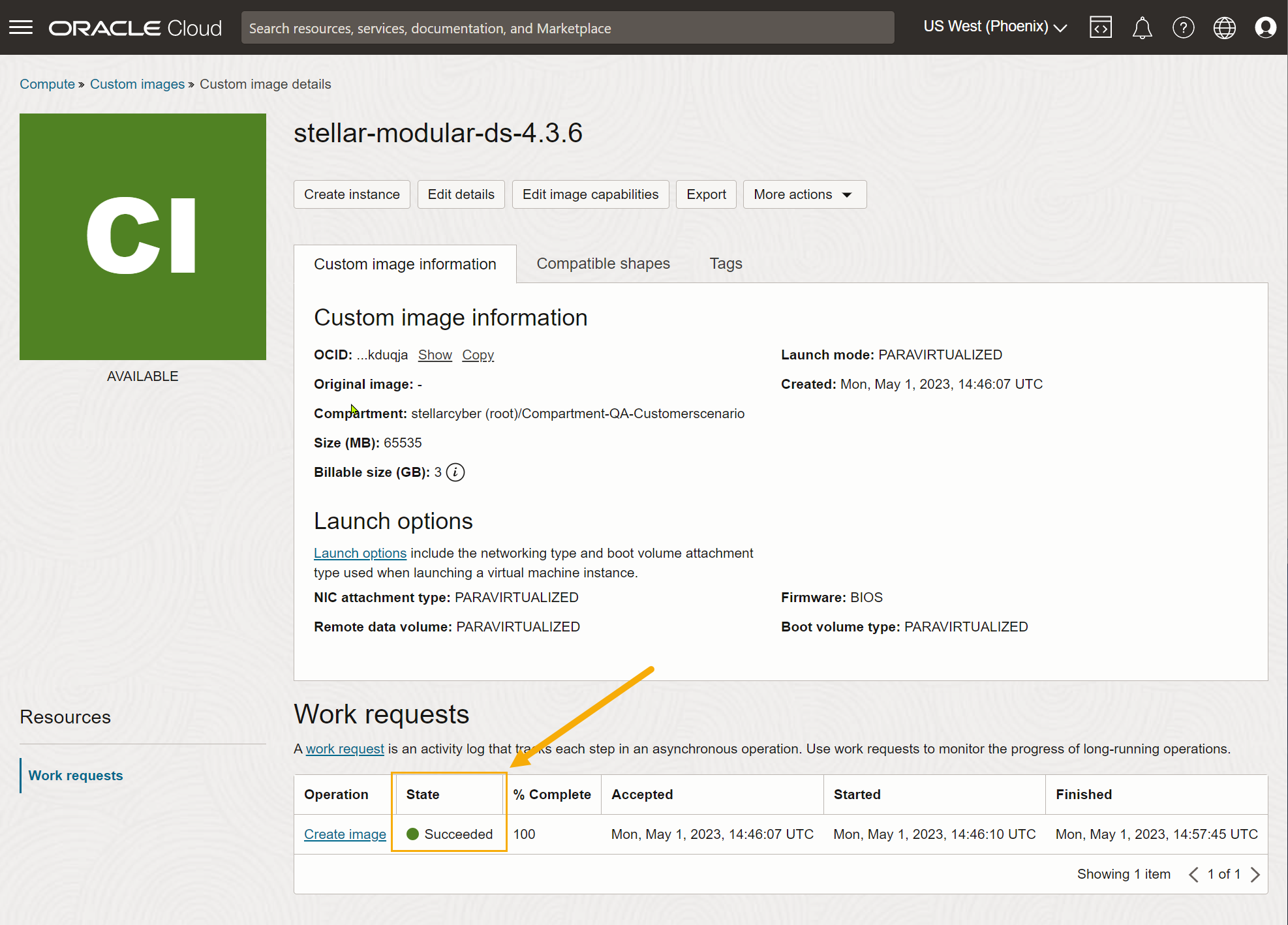
When you have finished configuring the settings in the Import image dialog box, click the Import image button to start the import process.
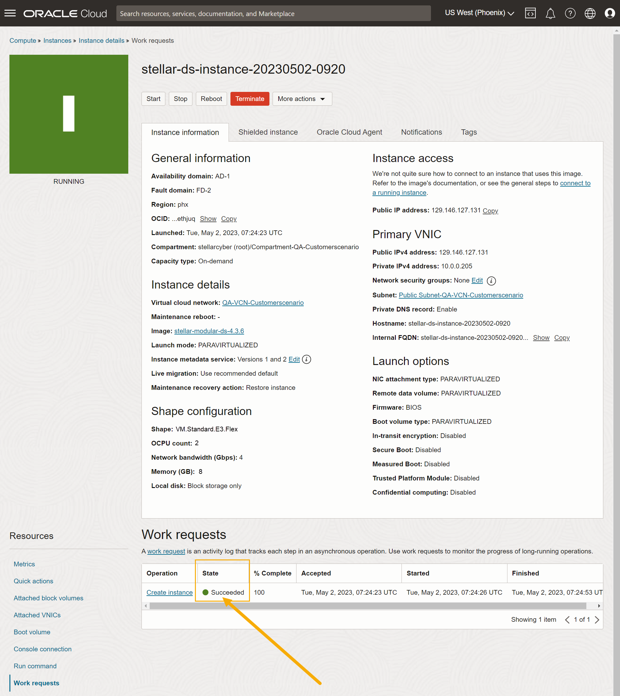
The Custom image details page appears for the image while it imports. When the image has finished importing, it appears with a value of Succeededin the State column, as shown below.
-
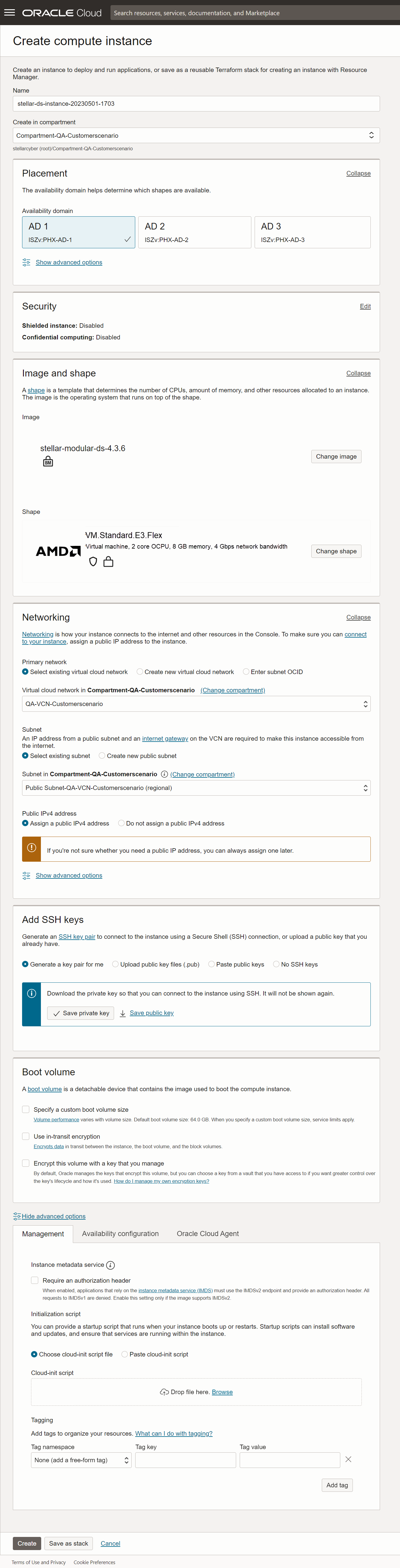
Once the image has finished importing, click the Create instance command to create a new instance based on the image. Set the options in the Create compute instance dialog box as follows:
-
Supply an easily identifiable Name for the new instance.
-
Choose the compartment and availability domain for the new instance. Make sure you choose the availability domain where you want to receive traffic.
-
Leave Image set to stellar-modular-ds-5.x.x.
-
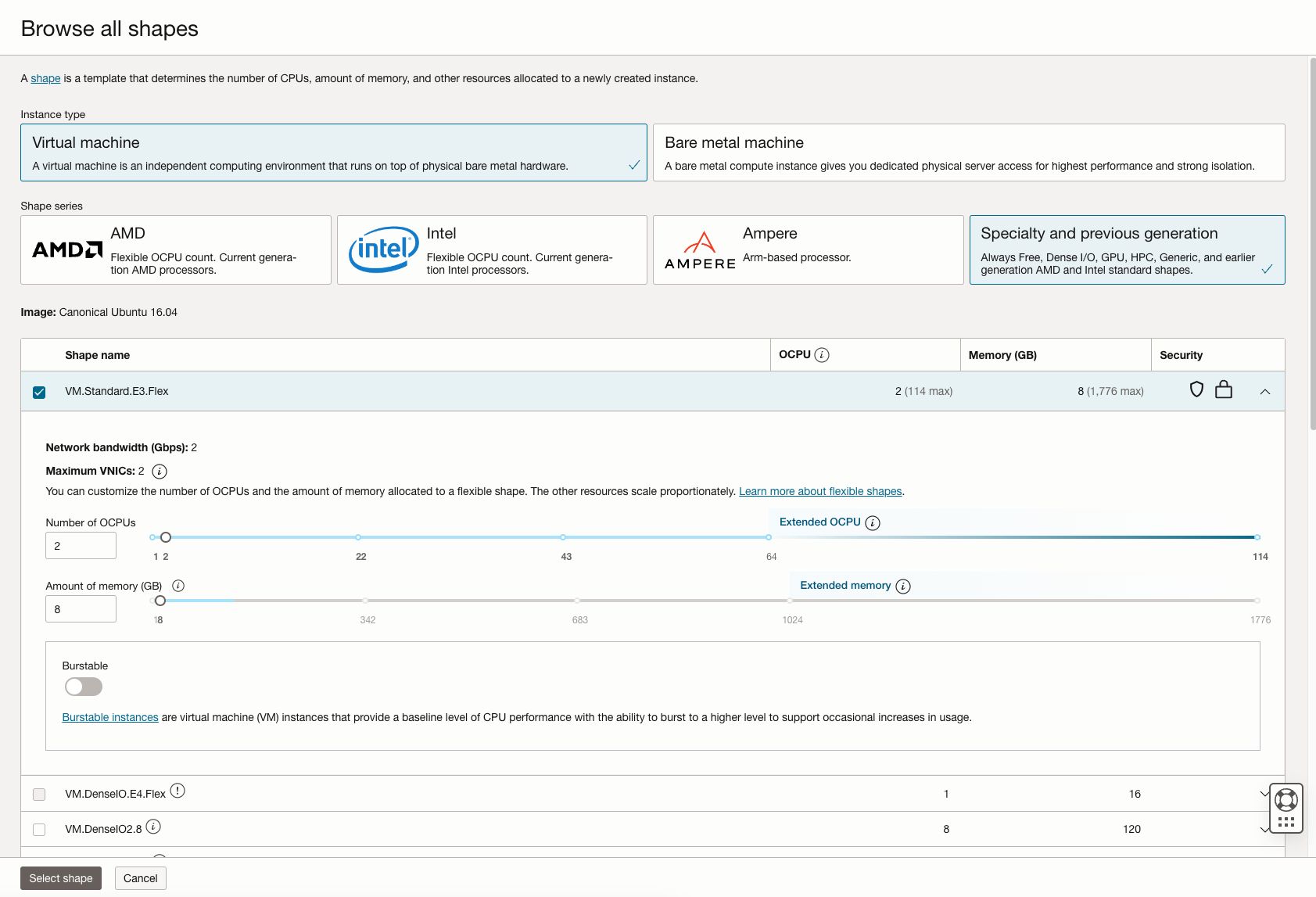
The Shape field lets you select from VMs with a variety of different provisioning. Choose a shape that corresponds to the resources required by the features to be enabled in this sensor's Sensor Profile.
You can customize the CPUs and memory for many of the available shapes by clicking Change shape and adjusting as necessary. For example, we know we want to enable the Log Collector, Log Forward, and Network Traffic features, so we've chosen the VM.Standard.E4.Flex shape and adjusted its settings to the minimum values of 4 CPUs and 6 GB of memory.
-
Use the Networking options to select the Primary network and Subnet for the sensor's management interface.
-
In most cases, you'll want to Assign a public IPv4 address to the management interface. This lets you manage the sensor from a DP located outside the OCI public cloud.
-
Use the Add SSH keys options to decide how you want to connect to the sensor using SSH. We are letting OCI generate a key pair for us and saving the resulting private key locally.
-
You can leave the other options set to their defaults.
The figure below shows our settings so far.
-
-
When you are satisfied with your settings, click Create to create the instance.
OCI begins to create the instance, tracking its progress in the Instance details | Work requests display. Once the State shown in the Work requests table shows Succeeded, as illustrated in the example below, you are ready to add a second VNIC to be used as a monitoring interface. See below.
Connecting the Sensor to the Stellar Cyber Platform
To connect the sensor to the Stellar Cyber Platform:
- Log in to your new sensor. The default username/password is aella/changeme. You are immediately prompted to change the password.
-
Change the password.
After you change the password, your session closes automatically. When you log back in with your new credentials, the prompt changes to DataSensor>.
-
Set the host name. The host name is displayed in Stellar Cyber and should be unique for each sensor:
set hostname <new hostname> -
If necessary, set the proxy HTTP server:
set proxy http://<proxy IP address:port>Note: The CLI prevents you from entering non-printable characters as part of the username or password for the proxy, as well as the proxy itself.
-
Optionally assign the tenant (if you skip this, the sensor is assigned to Root Tenant):
set tenant_id <Tenant ID from Stellar Cyber> -
Use the
set cmcommand to specify the IP address to reach the management interface of the Data Processor. For a DP cluster, this is the IP address of the DL-master's management interface. For a single DP deployment, this is simply the DP's management IP address. You can specify either an IP address or a hostname. For example:set cm 192.168.44.10or:
set cm example.company.comIf you specify a hostname rather than an IP address, the system attempts to verify the hostname with the DNS server. If the DNS server is not reachable, the system reports the error and lets you either proceed with the configured hostname or quit. This way, you can specify a hostname for the
set cmdestination in an offline environment without access to a DNS server. - Verify with the
show cmcommand. You should see the IP address of the DP listed as the CM Controller and the Status should be Established. -
When you added a second VNIC to the sensor VM, you recorded the IP address that OCI automatically assigned to it. Now, you need to assign that IP address within the sensor CLI. Use the following command:
Sensor > set interface ethernet1 ip <ip address assigned by OCI>For example:
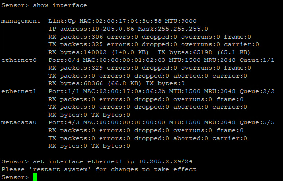
-
Use the
show timecommand to view the time zone.During installation, the timezone for sensors are automatically set to UTC+0. Since the logs for some security products may only include the local time without a timezone, Stellar Cyber recommends that you set the sensor timezone to the same timezone as your security product.
-
Use the
restart systemcommand to apply your changes.
Authorize the Sensor
You must authorize the sensor when it appears in the network.
You can authorize multiple sensors at a time. So if you're installing multiple sensors, install them all, then authorize them all at once.
Configuring a VTAP in OCI
There are many ways to configure traffic acquisition in OCI. In our example, we'll use the following technique:
-
We'll create a VTAP in OCI that mirrors traffic from a specific host whose traffic we want to monitor.
-
The mirrored traffic is sent to a Load Balancer in OCI that we'll also create.
-
We'll also create a capture filter for the VTAP to specify which traffic gets forwarded to the Load Balancer.
-
One of the targets of the Load Balancer is the management interface of the Modular Sensor.
-
Traffic sent from the Load Balancer to the management interface is encapsulated in VXLAN packets, so we'll enable and configure the AWS Mirror feature for our destination Modular Sensor in Stellar Cyber. As part of that configuration, we'll supply the VXLAN network identifier (VNI) of the VTAP so that the VXLAN traffic is parsed and the interior packets are read correctly by the sensor.
The procedures below show how to set up a deployment like this. Here's a summary of the configuration we're going to create:
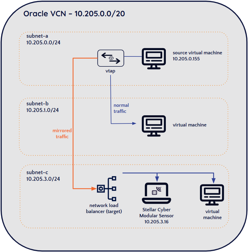
You might also want to refer to Oracle Cloud's documentation for the VTAP feature.
Create the Load Balancer and Point it at the Sensor's Management Interface
-
Click the main menu icon at the top left of the Oracle Cloud Console and select the Networking | Virtual cloud networks option.
-
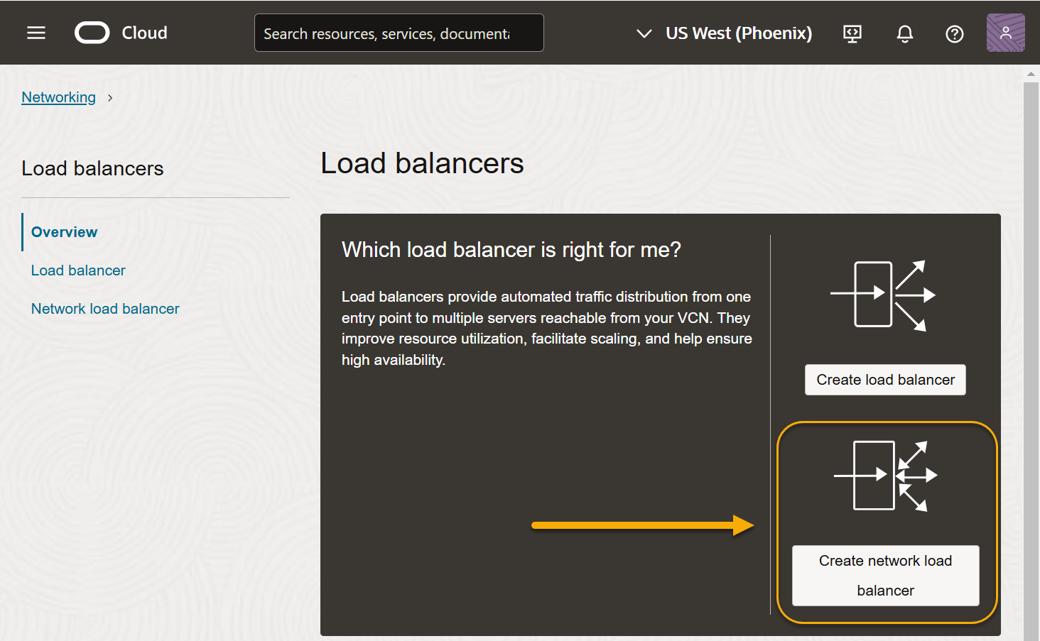
Click the Load balancers entry in the Networking menu at the left of the page. Then, click the Create network load balancer button to add a new network load balancer.
Make sure you create a network load balancer and not a regular load balancer. Only a network load balancer can serve as the destination for mirrored traffic from a VTAP.
-
Click Create load balancer.
-
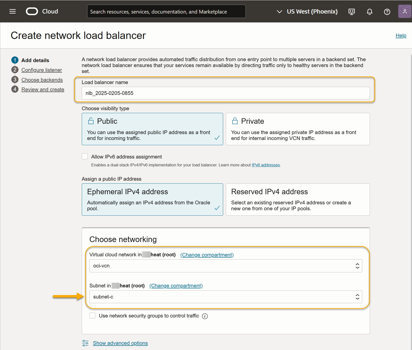
Supply a name for the load balancer and select a network and subnet. Make sure you select a network and subnet accessible to the modular sensor's management interface. For example, in the screenshot below, we're setting up the network load balancer in the same subnet as the modular sensor shown in the illustration at the start of this section (subnet-c):
-
Click Next and configure a logical listener for the load balancer.
-
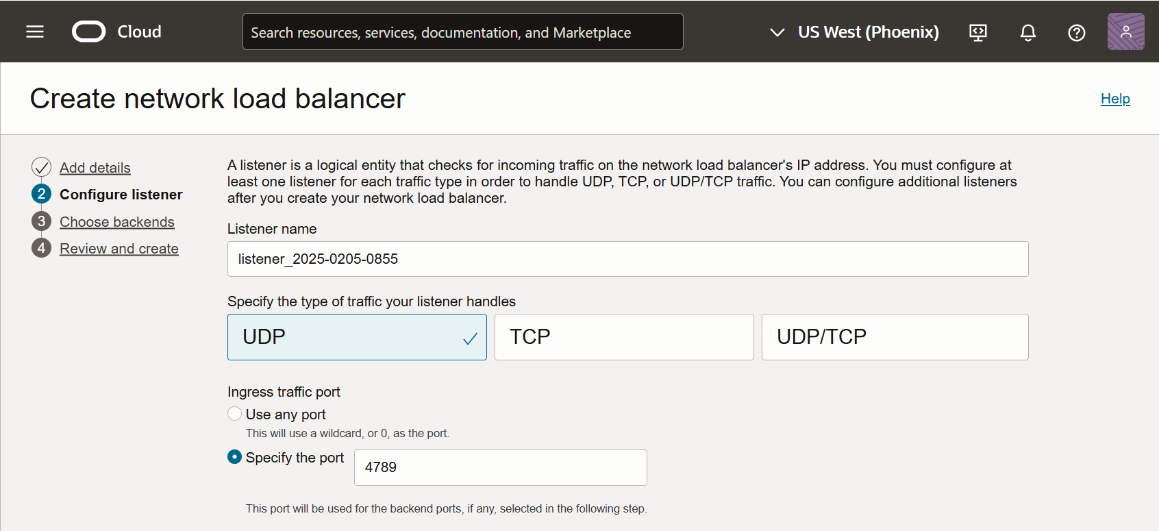
Supply a name for the listener.
-
Set the traffic type to UDP.
-
Set the Ingress traffic port to 4789.
For example:
-
-
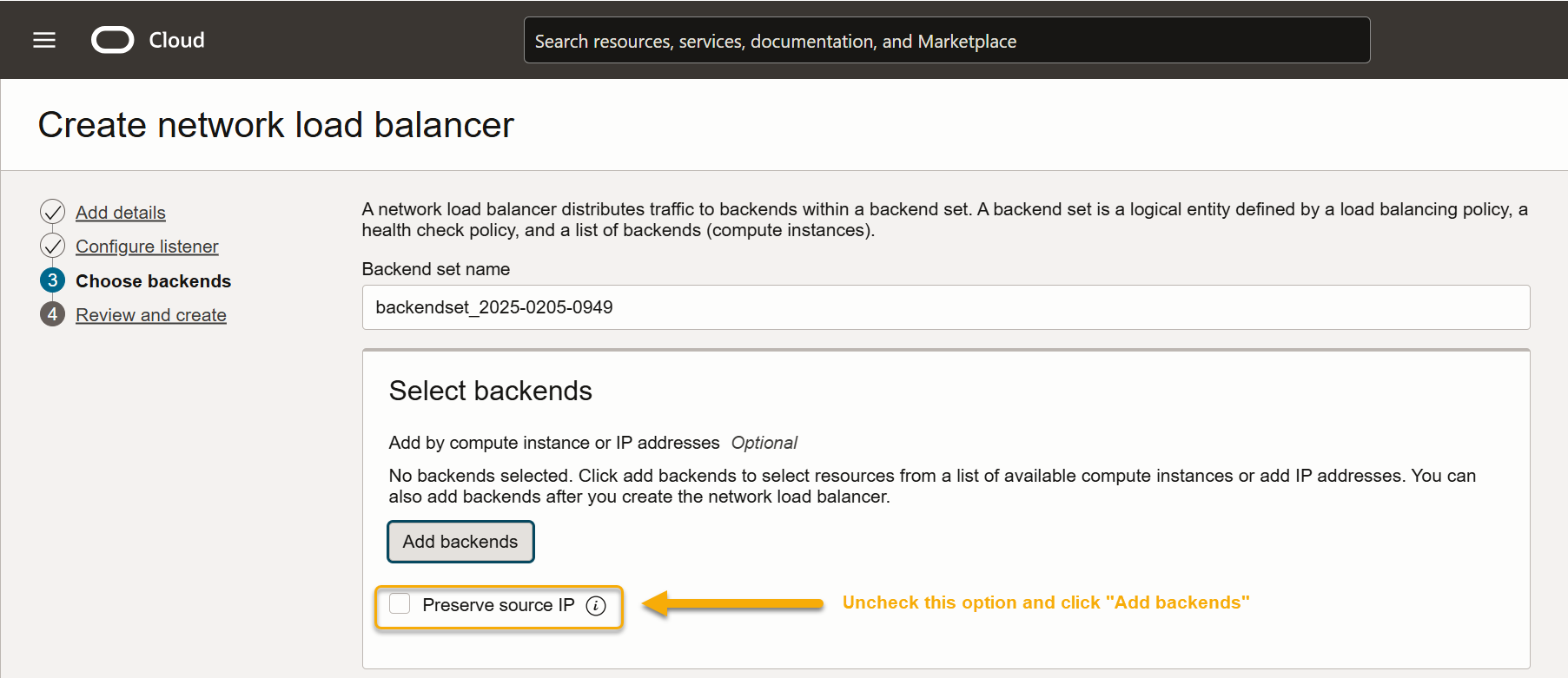
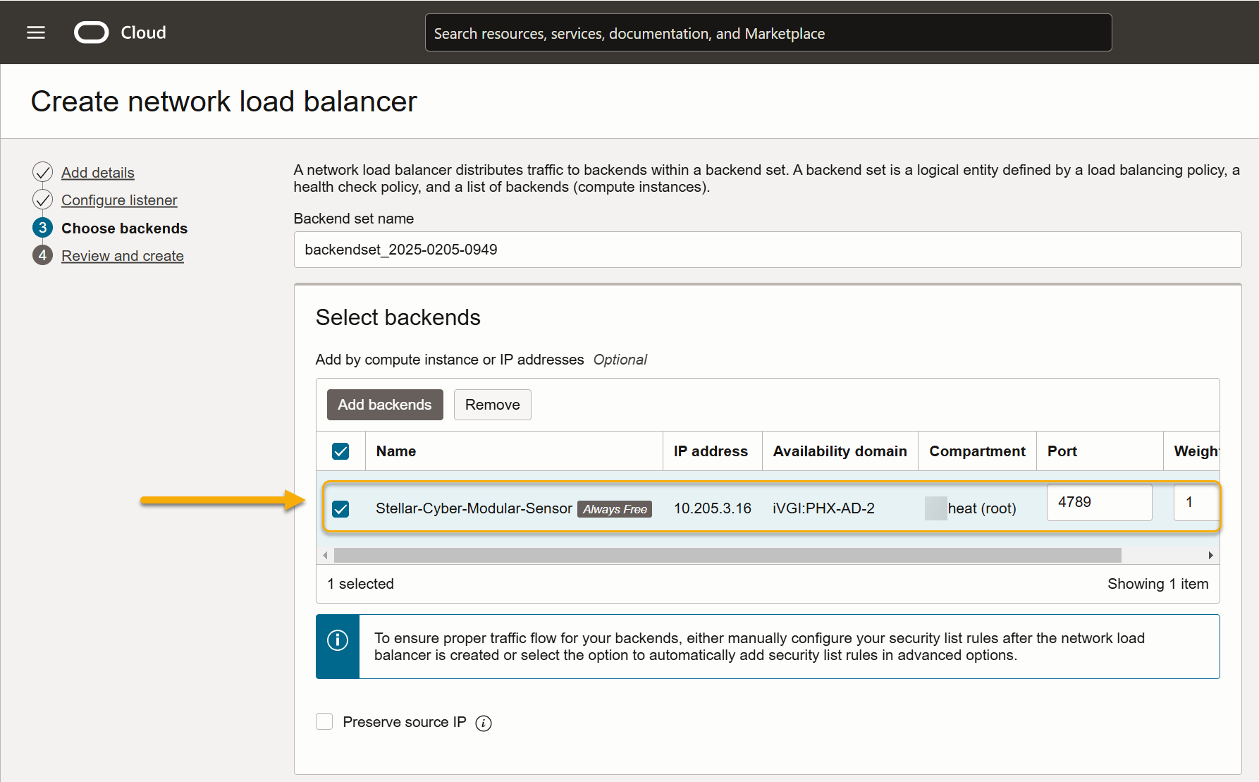
Click Next to display the Select backends screen. This is where we'll point the load balancer to the modular sensor VM's management interface.
-
Uncheck the Preserve source IP option and click the Add backends button.
-
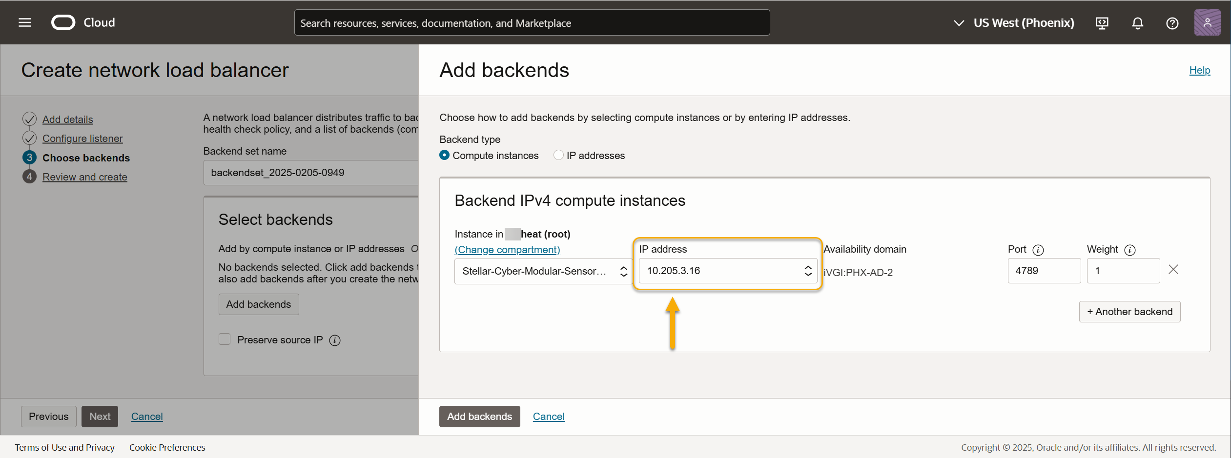
Use the Compartment and IP address fields to select the management interface of the modular sensor that we recorded during the installation of the sensor in the previous sections. In this example, we're selecting the IP address of the Modular Sensor's management interface shown in the illustration at the start of the section (10.205.3.16).
-
Click Add backends.
-
Select the new backend's entry in the Select backends list.
-
Health checks are mandatory for backends. To ensure successful health checks, you must set the Protocol and Port fields to an open port on the Modular Sensor's management port. Stellar Cyber suggests you use the default SSH port settings:
-
Protocol – TCP
-
Port – 22
-
-
Leave the Load balancing policy in the Advanced Options set to 5-tuple hash and click Next.
-
Click Create network load balancer to finish the creation of the load balancer.
The new network load balancer appears in the list.
You can click on the network load balancer's entry in the list to view a summary of its configuration. If the Source/destination header (IP, port) preservation and/or Symmetric hashing fields appear in this summary, ensure they are both set to disabled. If they are not, return to the configuration of your backend and make sure the Preserve source IP option is disabled.
Create the VTAP and Point it at the Load Balancer
-
Click the main menu icon at the top left of the Oracle Cloud Console and select the Networking | VTAPs option.
-
Click the Create VTAP button.
-
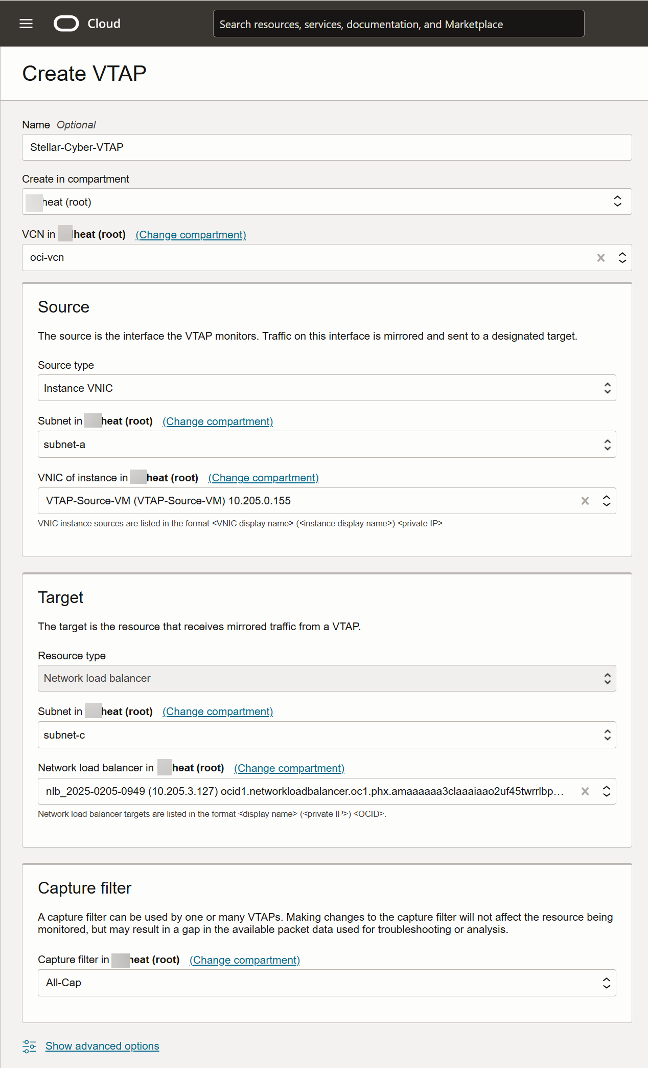
Supply a name for the VTAP.
-
Select the VCN for the VTAP. This should be the VNC where the VM whose traffic you want to monitor is located (oci-vcn in our example)
-
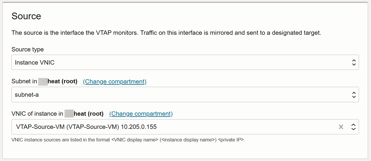
Use the Source fields to select the traffic the VTAP monitors. In this example, we're tapping the traffic on a specific instance's VNIC in subnet-a:
-
Source type is set to Instance VNIC
-
Subnet is set to subnet-a. This is the subnet for the VM whose traffic we want to monitor.
-
VNIC is set to the IP address of the instance we want to monitor 10.205.0.155 in this example).
Here's how the Source fields look for our example:
-
-
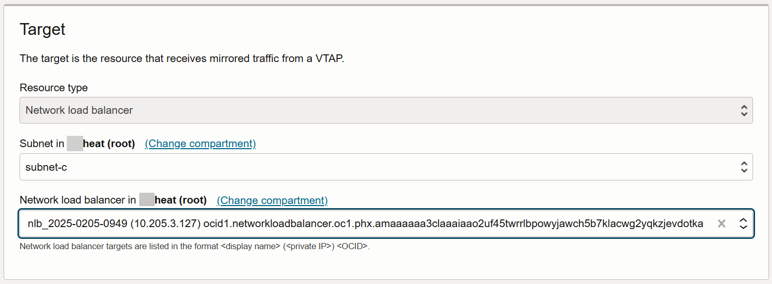
Use the Target fields to select where traffic monitored by the VTAP should be mirrored. The destination is the Network load balancer we created in the previous section. Here's how the Target fields look for our example:
-
Your VTAP must use a Capture filter. You can select an existing Capture filter or click the dropdown and use the Create new capture filter option to add a new one. In our example, we want all Ingress and Egress traffic. Here's how that filter looks as we create it:
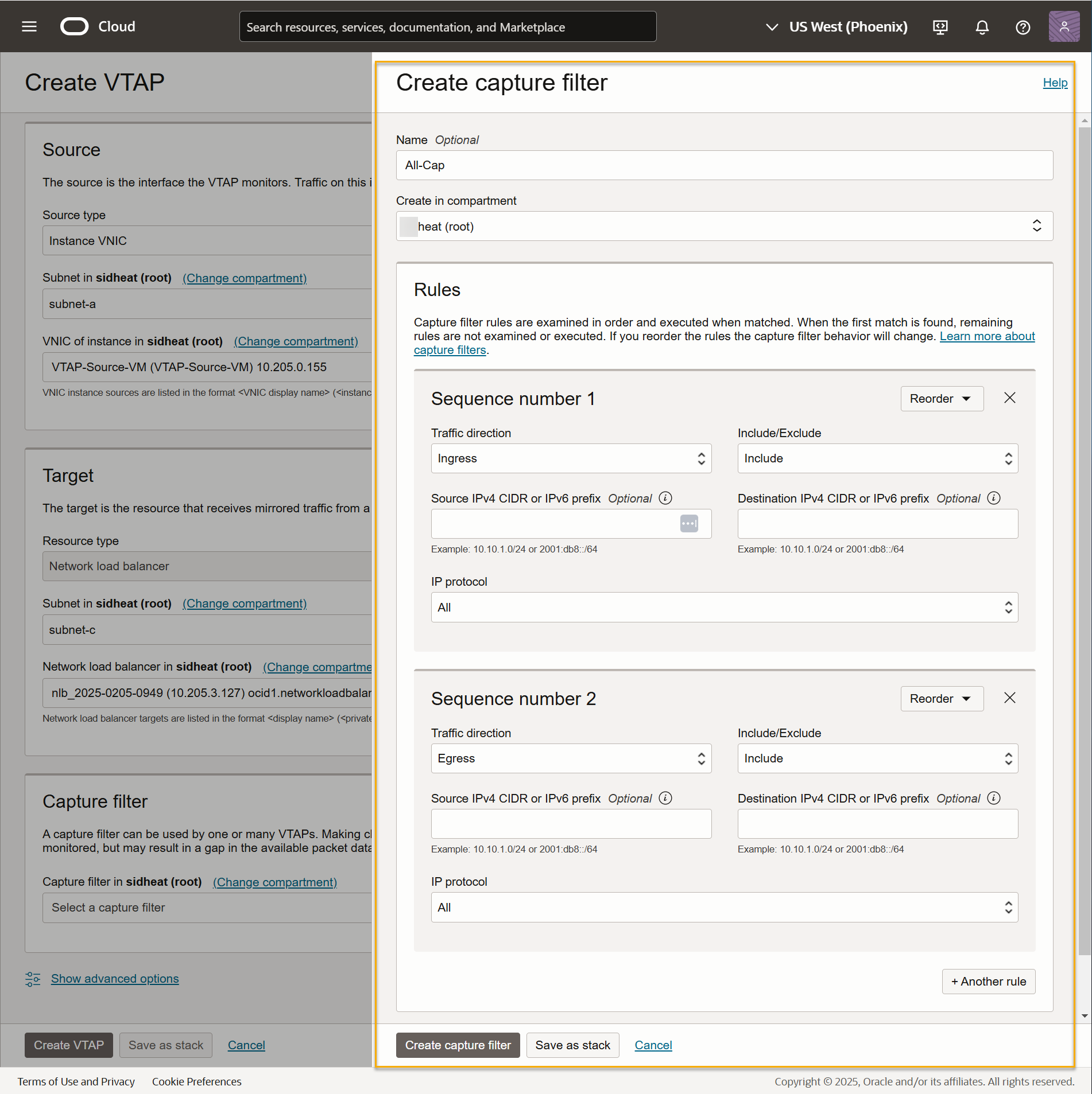
Here's our sample VTAP configured to send traffic from a specified VNIC to our load balancer with our new capture filter:
-
Click Create VTAP to add the VTAP.
-
A summary screen appears for your VTAP. Locate the VXLAN network identifier field and use the Copy button to save it in a text file. You will need to supply this identifier in Stellar Cyber in the next section.
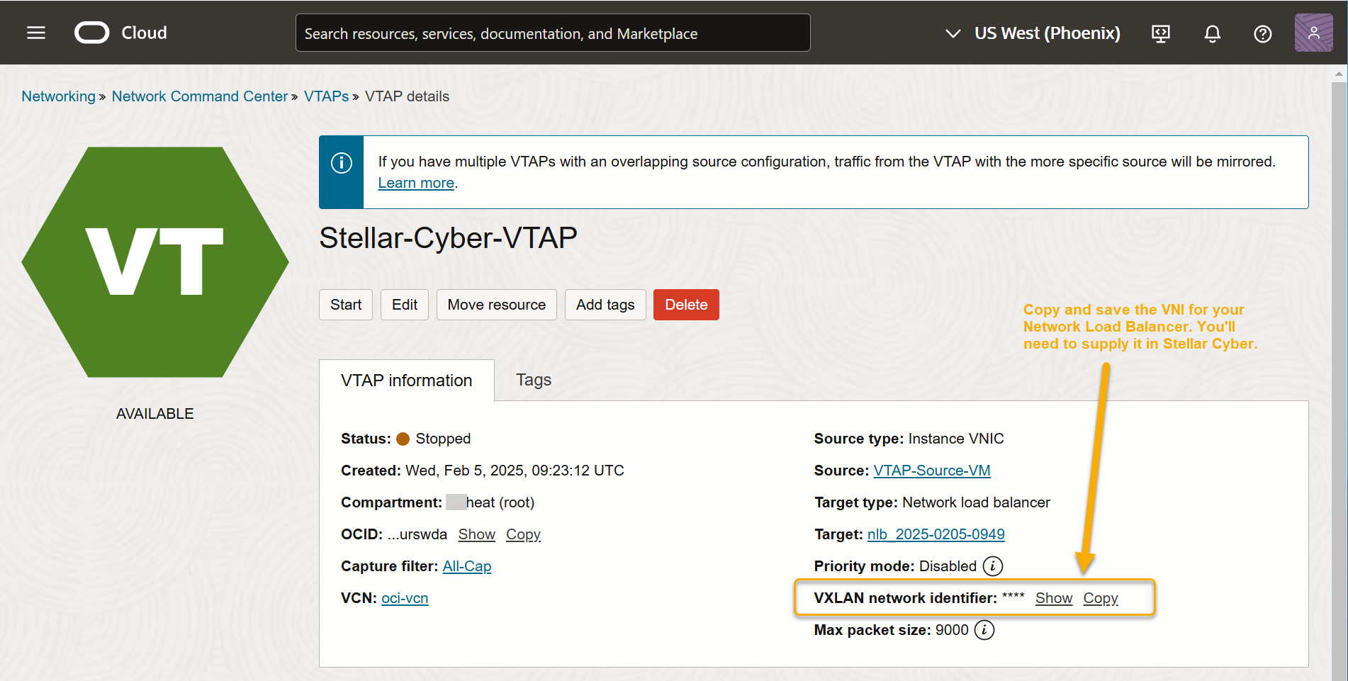
If you want to ingest traffic from multiple VTAPs with one Modular Sensor, you can assign the same VNI to each in OCI.
-
The VTAP does not start forwarding traffic until you click the Start button in the screen shown above. Click Start to begin forwarding traffic from this VTAP.
Enable the AWS Mirror Feature for the Destination Modular Sensor
Traffic sent from the load balancer to the modular sensor's management interface is encapsulated in VXLAN packets. You can configure the sensor to parse the VXLAN packets and read the encapsulated packets by enabling the AWS Mirror feature on the sensor. Use the following procedure:
Although the feature is called AWS Mirror, it can be used to enable VXLAN parsing on a sensor interface regardless of the actual source.
-
Log in to Stellar Cyber.
-
Go to System | Collection | Sensors. The Sensor List is displayed.
-
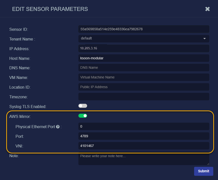
Click for the sensor used as the destination for the load balancer in OCI. The Edit Data Sensor Parameters window is displayed.
-
Enable AWS Mirror. Additional fields are displayed.
-
Set Physical Ethernet Port to 0. This is the default interface number for the Management Port on a Modular Sensor. You can verify interface assignments by using the
show vtepcommand on the sensor. -
Leave Port set to its default value of 4789.
-
Set VNI to the VXLAN ID for your VTAP in OCI. You copied this from the VTAP's summary screen in OCI in the previous section.
-
Click Submit. The parameters are immediately updated.
Verify Traffic
You can verify traffic flow from the monitored VM to the modular sensor's management port in the Threat Hunting interface:
-
Log in to the Stellar Cyber console and navigate to the Investigate | Threat Hunting page.
-
Set the Indices dropdown to Traffic.
-
Check the Sensors column in the table for traffic from the modular sensor used as the destination for the VTAP.
Enabling SSSE3 for the Modular Sensor VM
The Modular Sensor VM must have SSSE3 enabled for its processors in order to operate correctly. In most cases, SSSE3 will already be enabled. However, if you encounter issues with packet collection or Interflow data generation, you can use the instructions below to ensure that SSSE3 is enabled.
Sensors installed on Linux hosts must have SSSE3 enabled for their processors in order to operate correctly. This is true for Modular Sensors and Linux Server Sensors, as well as legacy Network and Security Sensors.
SSSE3 is typically supported/enabled for most vCPUs, but may not be for certain legacy AMD vCPUs. See below for instructions on enabling SSSE3.
To enable SSSE3 for a virtual machine:
-
Start the virtual shell (virsh)
-
Type the following command to edit the virtual machine's settings:
edit <virtual_machine_name> -
Locate the <cpu> section. It should appear similar to the following:
Copy<cpu mode='custom' match='exact' check='partial'>
<model fallback='allow'>SandyBridge</model>
......
</cpu> -
Add the following line to the <cpu> section:
<feature policy='require' name='ssse3'/>When you are done, the <cpu> section should appear similar to the following:
Copy<cpu mode='custom' match='exact' check='partial'>
<model fallback='allow'>SandyBridge</model>
<feature policy='require' name='ssse3'/>
...........
</cpu> -
Save changes to the virtual machine and exist virsh.
-
Run the following command:
virsh define /etc/libvirt/qemu/<virtual_machine_name>.xmlEach virtual machine has a configuration .xml file. Typically, these files are stored under /etc/libvirt/qemu, but the location may be different for your system.
-
Stop and start the virtual machine in virsh.
