Configuring Receivers
Receivers are configuration objects in Stellar Cyber that define destinations where data collected by Modular Sensors, Server Sensors, and connectors is sent for ingestion into the Data Processor (DP). Each Sensor Profile must refer to one or more receivers.
You must have Root scope to use this feature.
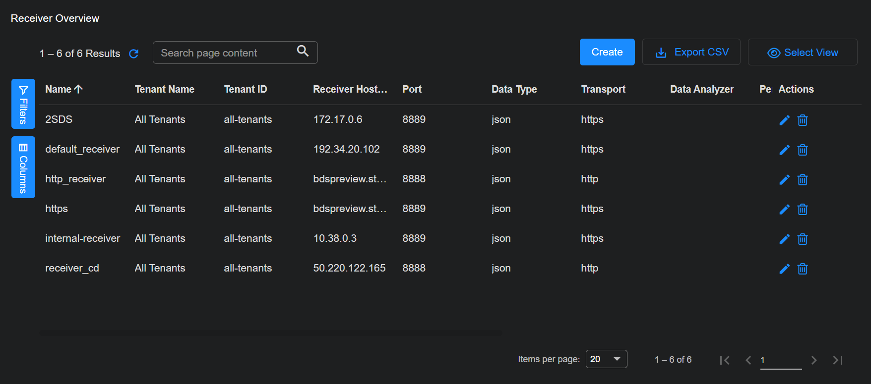
Receiver Overview
Select System | DATA SOURCE MANAGEMENT | Receivers to see a list of the configured receivers.
-
Select + Create to add a new receiver. A dialog box opens to add a receiver.
-
Select
 to edit the receiver on the corresponding row. A dialog box to edit the receiver appears.
 -
Select
 to delete the receiver on the corresponding row.
Adding a JSON Receiver
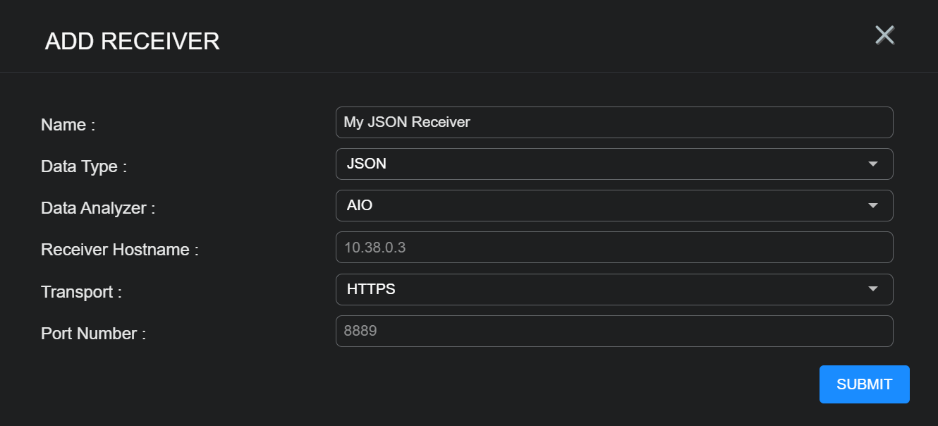
To add a JSON receiver, fill in the following fields:
-
Name – The name of the receiver. This value will be referred to by one or more sensor profiles. This field does not support multibyte characters.
-
Data Type – Choose JSON.
-
Data Analyzer – This field provides a selection list of available data analyzers. When one is selected, the IP address of the DA is entered into the following field. This field may be left blank.
-
Receiver Hostname – Enter the DNS name or IP address of the Data Processor or Data Analyzer that receives data from sensors and connectors in JSON format. This address identifies where structured telemetry such as logs, alerts, and Interflow data are sent. This field does not support multibyte characters.
-
Set this to the IP address or hostname of the DP in an All-in-One (AIO) deployment.
or
-
Set this to the IP address or hostname of the Data Analyzer master (DA-Master) in a cluster deployment.
-
-
Transport – Either HTTP or HTTPS. When this value is changed the Port Number is set to the default value.
Because HTTP transmits data unencrypted, use HTTPS when possible to prevent exposure along the network path.
-
Port – The TCP/IP port number on which the receiver listens for data packets.
Select Submit to save your changes. Select Cancel to dismiss the dialog box without saving your changes.
Adding a Packet Receiver 
Linux Server Sensors can forward captured network packets to legacy Security Sensors using VXLAN tunnels. This configuration uses a packet-mode receiver as described in this section. After the receiver is created, it can be assigned to a sensor profile that enables packet forwarding.
The overall configuration works as follows:
-
The sending Linux Server Sensor uses a Standard Server Sensor profile configured with two receivers:
-
A JSON receiver for standard analysis tasks.
-
A packet receiver with the VXLAN transport type, which specifies the destination for the forwarded packet data in the Receiver Hostname field.
-
The sending Linux Server Sensor also has Packet Forwarding enabled in its Standard Sensor Profile.
-
-
The receiving legacy Security Sensor has a packet receiver with VXLAN enabled.
Packet receivers that use VXLAN transport are supported only when the destination is a legacy Security Sensor. Modular Sensors cannot be used as VXLAN destinations, even when the Sandbox and IDS features are enabled. Modular Sensors capture network traffic directly through SPAN or TAP interfaces or aggregate telemetry through JSON receivers, not VXLAN tunnels.
If you configure a packet receiver that targets a legacy Security Sensor without a SPAN or TAP port, that sensor cannot analyze its own local network traffic for malware or IDS events. It will process only the VXLAN-forwarded packets it receives from other sensors such as Linux Server Sensors.
To maintain malware and IDS analysis for the Security Sensor environment, you must do one of the following:
-
Configure another Security Sensor (or a Modular Sensor with the Sandbox and IDS features enabled) and forward traffic to that sensor instead.
-
Remove the packet receiver if it's not required.
-
Reassign the receiver to a different Security Sensor that has an active SPAN or TAP feed.
In other words, a Security Sensor without a SPAN or TAP connection can analyze only the traffic forwarded to it—it cannot analyze its own network traffic.
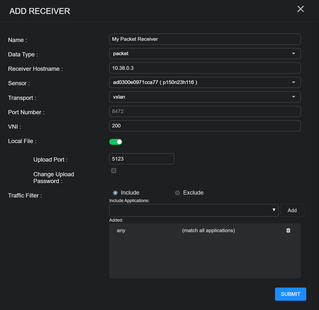
To add a packet receiver, fill in the following fields:
-
Name – Enter the name of the receiver. This field does not support multibyte characters.
-
Data Type – Choose Packet.
-
Receiver Hostname – Enter the IP address or domain name of the destination legacy Security Sensor that will receive VXLAN-encapsulated packet data from a Linux Server Sensor. This field does not support multibyte characters.
-
Sensor – Displays the receiver sensor associated with the hostname entered above. This field is automatically populated and cannot be changed manually. The sensor must be a legacy Security Sensor configured to receive VXLAN traffic.
-
Transport – Currently set only to the value VXLAN.
-
Port – The TCP/IP port number on which the receiver listens for data packets. Common VXLAN port options are 4789 or 8472.
-
Local File Configuration – This assembles files on the sensor and sends the files via TLS to the legacy Security Sensor. Because this action requires the sensor to process the files, enabling it can impact performance. When Enable Local File is toggled on, the additional fields for Upload Port and Configure Password appear.
Local file assembly functions only on sensors with the Network Traffic feature enabled. When enabled, file assembly responsibilities shift from the destination Security Sensor to the sending sensor, which can increase CPU utilization on that sensor. Do not enable local file assembly if other server sensors are also forwarding data to the same Security Sensor, as this can cause redundant processing and performance degradation.
-
Upload Port – The UDP port number of the target device that will receive packets. Default is 5123.
-
Configure Password – When checked this enables the password fields.
-
Upload Password and Re-enter Password – Use these fields to set the password that the sensor uses when sending packets to the target sensor.
-
-
VXLAN Configuration
-
VNI – The Virtual Network Interface. This value should be left at the default of 200.
-
Traffic Filter – Stop forwarding (filter) IDS and malware traffic for the selected applications. If the VXLAN has too much traffic, use this filter to limit the traffic sent. To configure the traffic filter:
-
Choose whether to Include or Exclude.
If you have a small subset of applications to monitor, choose Include. You must explicitly include each application you want analyzed; any application not listed is filtered out. The default value is any, which allows all traffic. The traffic filter operates at the application-protocol layer and applies only to IDS and malware analysis traffic. Use it to reduce VXLAN bandwidth when unnecessary application flows generate excess traffic.
If you want to include most applications and exclude a subset, choose Exclude. If an application is excluded, its traffic is filtered out. The default is none.
-
Choose one or more applications from the Applications drop-down list.
Start typing and Stellar Cyber narrows down the list. The first application you add replaces the default. You can add as many applications as you want.
-
Select the X to remove an application from the list.
-
When done, select Submit.
The receiver is updated.
-
-
