Using a Modular Sensor with Azure Virtual Network TAP (VTAP)
This topic describes how to use a Stellar Cyber Modular Sensor with Microsoft Azure's Virtual Network TAP (VTAP). You can use Microsoft Azure VTAP to mirror network traffic from one or more Azure source NICs to a Stellar Cyber Modular Sensor, either through an internal load balancer or directly. Traffic is mirrored using VXLAN encapsulation over port 4789. The Modular Sensor receives the mirrored traffic, analyzes it, and forwards Interflow records and detections to the Stellar Cyber Platform.
Caution – Start Slowly and Expand Gradually
Azure Virtual Network TAP is currently in Public Preview and does not enforce limits on how many source NICs can be mirrored to a single destination. Because mirrored traffic is additive, mirroring a large number of high-volume sources — such as every NIC in a production subnet or a firewall interface — to a single Modular Sensor or load balancer frontend can quickly saturate the destination subnet's bandwidth.
Plan your VTAP configuration carefully and keep the following in mind:
- Start with a small number of source NICs and expand gradually while monitoring bandwidth utilization on the destination subnet.
- Avoid mirroring high-traffic interfaces without first estimating the expected traffic volume against your sensor's capacity.
- Where possible, use an internal load balancer with multiple Modular Sensors in the backend pool to distribute the mirrored traffic load.
- Monitor the Modular Sensor's network interface utilization after enabling the VTAP and be prepared to remove source mirror configurations if saturation is detected.
-
Azure VTAP Network Architecture – Internal Load Balancer vs. Direct Connection
-
Enabling the AWS Mirror Feature for the Destination Modular Sensor
For full details on the Azure VTAP, refer to Microsoft's documentation, beginning with the Azure Virtual Network TAP Overview.
Azure VTAP Network Architecture – Internal Load Balancer vs. Direct Connection
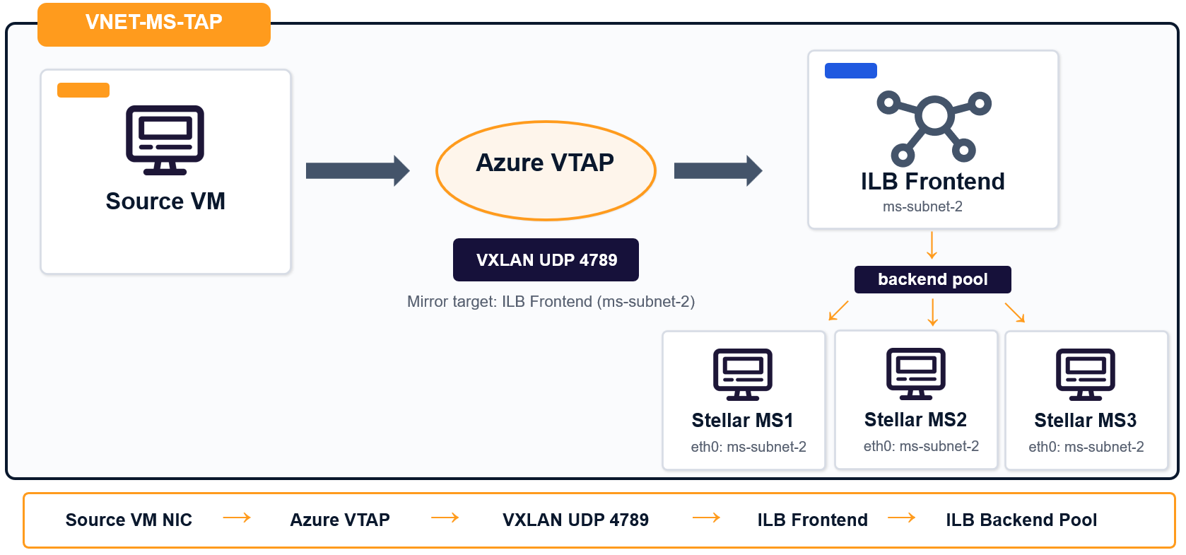
You can deploy the VTAP using either an Azure Internal Load Balancer with one or more Modular Sensors connected to the load balancer's backend pool, or a direct connection to the Stellar Cyber Modular Sensor:
-
Using a Standard internal load balancer sends Azure VTAP traffic to the load balancer frontend instead of directly to one NIC. The load balancer then distributes the mirrored VXLAN traffic across multiple Modular Sensors in the backend pool. This approach is better when you need higher availability or want to scale traffic collection across multiple sensors without changing the Azure VTAP destination later.
In this model, the Modular Sensor must use only a single NIC (eth0). You add this NIC to the load balancer's backend pool.
-
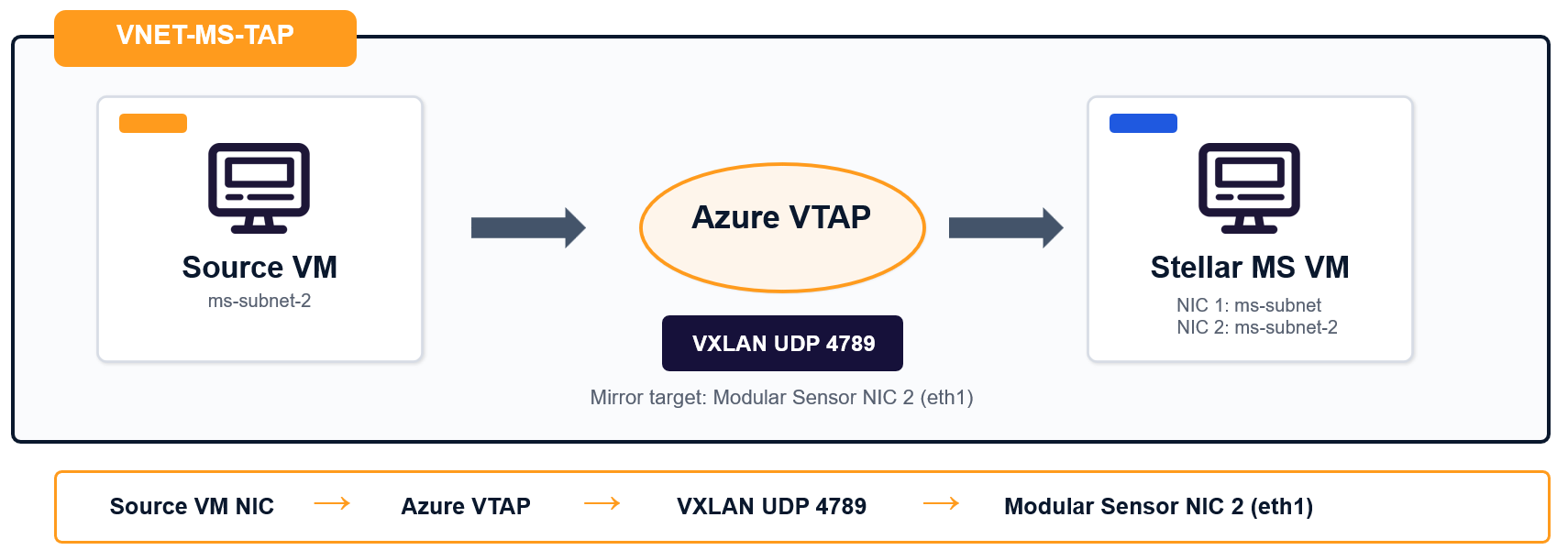
Using a direct connection sends Azure VTAP traffic to the collector NIC on a single Modular Sensor. This approach is simple and works well when you only need one sensor.
In this model, the Modular Sensor requires two NICs. The second NIC (eth1) is used as the destination for mirrored traffic from the VTAP.
Prerequisites
Before you configure Azure VTAP, make sure your deployment meets the following requirements:
|
Requirement |
Details |
|---|---|
|
Azure Subscription |
The subscription must have the Refer to Enabling the Azure VTAP Feature. |
|
Supported Region |
Make sure you are deploying in a region that supports Azure VTAP. Azure VTAP is currently in public preview; not all regions are supported. At this writing, East US, North Europe, West Europe, and others are all supported. However, West US and West US 2 are not. |
|
Existing Azure Networking |
You need an existing virtual network with at least two subnets (one for sensor management and one for collection from the VTAP). |
|
Modular Sensor Deployed |
You must have a Modular Sensor running 6.4.0 or later deployed. If you are mirroring traffic directly to the Modular Sensor without using a load balancer, the sensor must have two NICs (one for management and the other for data collection). Note that the default Modular Sensor deployment script only creates a single NIC. See Deploying the Modular Sensor in Azure for instructions on adding a second NIC. |
|
Azure Permissions |
You need permissions to create or modify virtual network, NIC, VTAP, peering, and Network Security Group resources. The Contributor role typically provides the necessary permissions. |
|
Execution environment |
The instructions in this topic use Azure Cloud Shell. However, you can also perform the procedures in this topic from the Azure Portal. |
Enabling the Azure VTAP Feature
The Azure VTAP is currently in public preview mode and must be enabled for your subscription.
-
You can check your subscription with the following command from the Azure Cloud Shell:
az feature list --namespace Microsoft.Network --query "[?contains(name, 'Tap')].{Name:name, State:properties.state}" -o table
-
This command returns the status of the
Microsoft.Network/AllowVirtualNetworkTapfeature. If the feature isNotRegistered, register it with the following command:az feature register --namespace Microsoft.Network --name AllowVirtualNetworkTap
The feature must leave the Pending state and reach the Registered state before you can create Azure VTAP resources. You can continue to check the status with the command in the first step.
Checking Azure Allowed Locations Policy
If your subscription is governed by an Allowed Locations policy, make sure the target region is allowed.
- In the Azure portal, go to Management Groups.
- Select the management group that applies to the subscription.
- Go to Governance > Policy > Assignments.
- Open the Allowed locations policy assignment.
- Select Edit and add the target region if it is not already allowed.
Deploying the Modular Sensor in Azure
This topic assumes you have already deployed the Modular Sensor you want to use as the destination for mirrored traffic from the Azure VTAP, authorized it, and connected it to the Stellar Cyber Platform.
If you have not already done so, use the instruction in Installing a Modular Sensor in Azure.
Keep in mind the following when deploying the Modular Sensor:
-
The number of NICs required on the sensor depends on whether you are mirroring traffic through an internal load balancer or directly to the sensor:
-
Internal Load Balancer – Deploy with a single NIC (eth0) and mirror traffic to it. This is the default deployment configuration.
-
Direct Connections – Deploy the sensor with two NICs and mirror traffic to the second NIC (eth1). The second NIC is attached to the subnet used for collection from the VTAP.
The Modular Sensor installation script for Azure creates only a single NIC by default. Refer to Adding a Second NIC to the Modular Sensor (Direct Connections) for instructions on how to add a second NIC.
-
-
The Network Traffic option must be enabled in the Modular Sensor profile assigned to the sensor so that it can monitor mirrored traffic and forward the resulting metadata to the Stellar Cyber Platform.
-
The VM size must support your expected workload.
Configuring the "AWS Mirror" Feature for the Modular Sensor
Traffic sent from the Load Balancer to the Modular Sensor is encapsulated in VXLAN packets, so as a last step, you'll enable and configure the AWS Mirror feature for the destination Modular Sensor in Stellar Cyber. As part of that configuration, you'll supply the VXLAN network identifier (VNI) of the VTAP so that the VXLAN traffic is parsed and the interior packets are read correctly by the sensor.
Adding a Second NIC to the Modular Sensor (Direct Connections)
The installation script for a Modular Sensor creates only a single NIC by default. If you are using a direct connection from the VTAP to the Modular Sensor, you must add a second NIC to the Modular Sensor using the procedure below.
Keep in mind that the new NIC must be in the same subscription, region, and virtual network as the virtual machine. The NIC will be in a different subnet than the existing NIC, but not a different virtual network. In addition, you will need to stop (deallocate) the virtual machine temporarily while you attach the NIC.
The table below summarizes the NICs for the Modular Sensor in a direct connection deployment:
|
NIC |
Interface |
Role |
Public IP |
|---|---|---|---|
|
NIC 1 |
|
Management access and communication with the Stellar Cyber Platform |
Yes |
|
NIC 2 |
|
VTAP collector interface for mirrored VXLAN traffic |
No |
Instructions are provided below for both the Azure Portal and CLI.
Adding a Second NIC in the Azure Portal
- Log in to the Azure portal.
- Open the Sensor VM.
- Stop the Sensor VM and wait until the status changes to Stopped (deallocated).
- In the VM menu, select Networking.
- Select Attach network interface.
- Select an existing NIC or create a new NIC.
- If you create a new NIC, place it in the same virtual network as the Sensor VM's existing NIC and select the correct subnet for the second interface.
- Attach the NIC to the Sensor VM.
- Start the Sensor VM.
Adding a Second NIC in the Azure CLI
-
Open the Azure Cloud Shell and select Switch to Bash.
-
Create the second NIC with the following command:
Copyaz network nic create \
--resource-group <resource-group> \
--name <nic-name-2> \
--vnet-name <virtual-network-name> \
--subnet <subnet-name> \
--network-security-group <nsg-name> -
Deallocate (stop) the virtual machine, attach the NIC, and then start the virtual machine:
Copyaz vm deallocate \
--resource-group <resource-group> \
--name <sensor-vm-name>
az vm nic add \
--resource-group <resource-group> \
--vm-name <sensor-vm-name> \
--nics <nic-name-2>
az vm start \
--resource-group <resource-group> \
--name <sensor-vm-name>
Verifying the New NIC
After the Sensor VM starts, verify the following:
- The new NIC is attached to the Sensor VM.
- The NIC has the expected IP configuration.
- The Network Security Group and subnet assignments are correct. This second NIC will collect traffic from the Azure VTAP. It should be in the subnet that receives mirrored VXLAN traffic over UDP port 4789.
Configuring Network Peering
You can deploy the Modular Sensor either in the same network as the VM whose traffic it will monitor or in separate networks. Deploying in the same network is typically simpler because you do not need to configure virtual network peering. Examples of each are provided below:
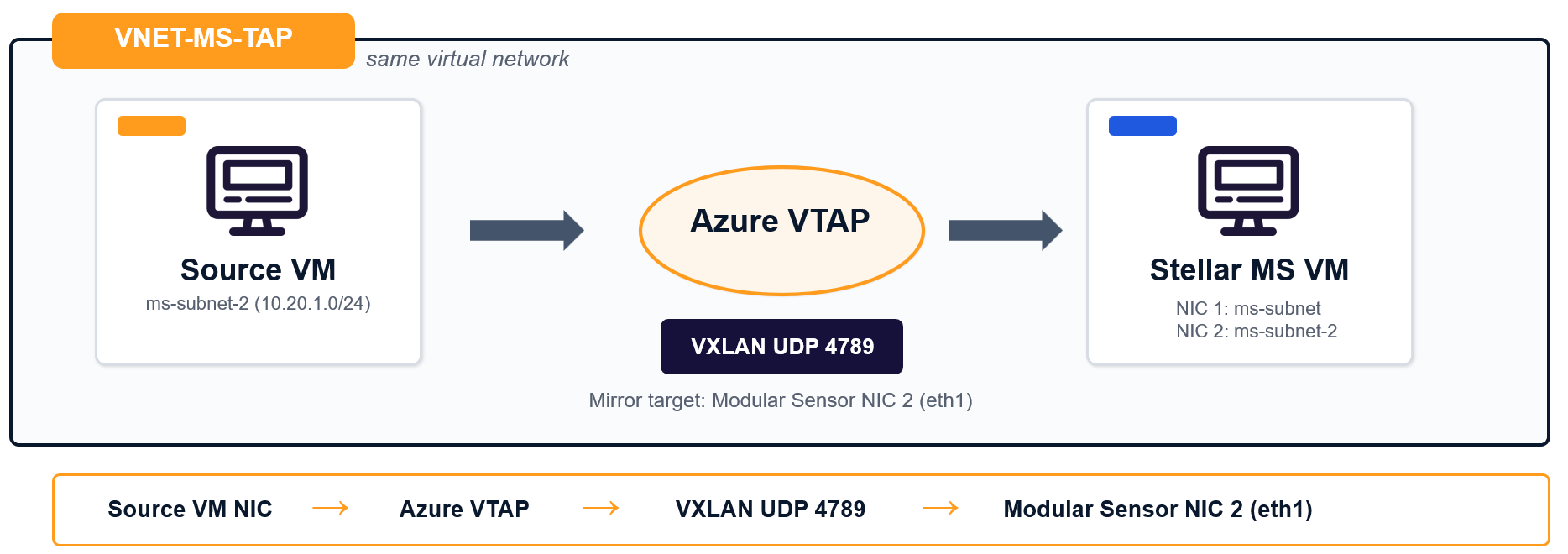
Deploying in the Same Virtual Network
In this example, both virtual machines reside in the same virtual network (VNET-MS-TAP). The Azure VTAP mirrors traffic from the source VM NIC to NIC 2 on the Modular Sensor using VXLAN UDP 4789.
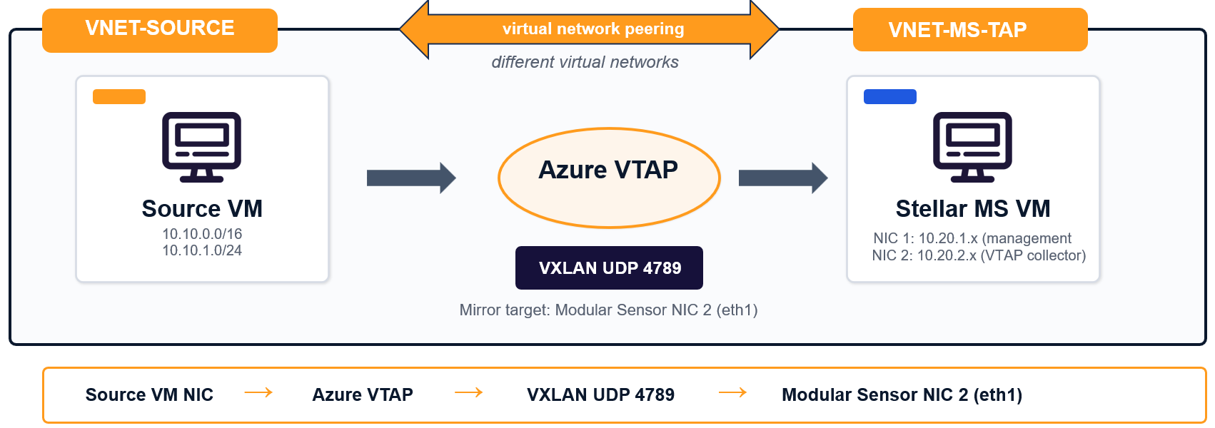
Deploying in Different Virtual Network with Virtual Network Peering
In this example, the source machine resides in a different virtual network (VNET-SOURCE) than the Modular Sensor VM (VNET-MS-TAP). The Azure VTAP still mirrors traffic from the source VM NIC to NIC 2 on the Modular Sensor using VXLAN UDP 4789, but virtual network peering must be configured between the two networks. Virtual network peering lets resources in the two virtual networks communicate over the Azure backbone.
Configuring Virtual Network Peering
The script below creates bidirectional peering between the source virtual network and the virtual network where the Modular Sensor VM resides.
SOURCE_VNET_ID=$(az network vnet show -g "$RG" -n VNET-SOURCE --query id -o tsv)
MS_VNET_ID=$(az network vnet show -g "$RG" -n "$VNET_NAME" --query id -o tsv)

az network vnet peering create -g "$RG" --vnet-name VNET-SOURCE \
    -n source-to-ms --remote-vnet "$MDS_VNET_ID" --allow-vnet-access
az network vnet peering create -g "$RG" --vnet-name "$VNET_NAME" \
    -n ms-to-source --remote-vnet "$SOURCE_VNET_ID" --allow-vnet-access

az network vnet peering list -g "$RG" --vnet-name VNET-SOURCE \
    --query "[].{Name:name, State:peeringState}" -o table
What the Script Does
- Retrieves the Azure resource ID for the source virtual network named
VNET-SOURCE. - Retrieves the Azure resource ID for the virtual network named in
$VNET_NAME. - Creates a peering named
source-to-msfromVNET-SOURCEto the remote virtual network. - Creates a peering named
ms-to-sourcefrom the MS virtual network back toVNET-SOURCE. - Lists the peering state for
VNET-SOURCEso you can verify that the relationship is connected.
Why Two Peering Commands Are Required
Azure virtual network peering is configured from the perspective of each virtual network. For that reason, the script creates one peering object in each direction. When both peerings are configured successfully, the virtual networks can exchange traffic according to the peering settings and any applicable Network Security Group rules.
The procedures below explain how to configure both an internal load balancer deployment and a direct connection in either the Azure Portal or the CLI.
Configuring Azure VTAP in the Azure Portal
Configuring the Azure VTAP in the Azure Portal consists of the following major steps:
-
If you are using the load balancer deployment model, start by creating the standard internal load balancer.
-
Set the destination of the VTAP. You do this differently depending on whether you are using a direct connection or an internal load balancer:
-
Internal Load Balancer – Set the destination to the frontend IP configuration of a standard internal load balancer. In this deployment, the management NICs (eth0) on one or more Modular Sensors are connected to the load balancer's backend pool.
-
Direct Connection – Set the destination of the VTAP to the collector NIC (NIC2/eth1) on the Stellar Cyber Modular Sensor.
-
-
Add the VTAP configuration to the source VM NICs so Azure can mirror traffic to the collector over UDP port 4789.
Azure VTAP does not support packet-selection filters in the VTAP configuration. When you attach VTAP to a source NIC, Azure mirrors that NIC’s traffic to the configured destination. To reduce what is analyzed, scope the tapped NICs carefully or filter traffic on the Sensor side.
You can also configure an Azure VTAP deployment in the CLI.
Create a Standard Internal Load Balancer in the Azure Portal
Use a Standard internal load balancer when you want Azure VTAP to send mirrored traffic to a load balancer frontend instead of directly to a single Modular Sensor NIC. The load balancer can then distribute the mirrored traffic to the management (eth0) ports of one or more Modular Sensors in the backend pool. Azure supports internal load balancers with a frontend IP configuration, backend pool, health probes, and load-balancing rules, all of which can be configured in the Azure portal.
Before You Begin
- Use the Standard SKU.
- Use the Internal load balancer type. Do not assign a public IP address.
- Place the load balancer in the same virtual network as the subnet used for modular sensor VTAP collector NICs.
- Use an HA Ports rule so all protocols and ports pass through the load balancer. This ensures VXLAN UDP 4789 is forwarded without creating a port-specific load-balancing rule.
- For Azure VTAP, the destination must be the frontend IP configuration resource ID of the load balancer (not the load balancer resource ID and not a NIC resource ID)
Create the Load Balancer
- Log in to the Azure portal.
- In the search bar, enter Load balancers, then open Load balancers.
- Select Create.
- In the Basics tab, select the correct Subscription and Resource group.
- Enter a name for the load balancer.
- Select the correct Region.
- Set SKU to Standard.
- Set Type to Internal.
- Select Next: Frontend IP configuration.
Add the Frontend IP Configuration
- Select Add a frontend IP configuration.
- Enter a name for the frontend IP configuration.
- Select the virtual network that contains the Modular Sensor VTAP collector NICs.
- Select the subnet used for the collector side (the subnet that contains the management ports for your destination Modular Sensors).
- Choose a private IP assignment method that matches your design.
- Save the frontend IP configuration.
For Azure VTAP, this frontend IP configuration is the object you later use as the VTAP destination. Azure VTAP sends mirrored traffic to the destination IP configuration you specify here.
Create the Backend Pool
- Select Next: Backend pools.
- Select Add a backend pool.
- Enter a name for the backend pool.
- Choose the backend pool configuration method used by your deployment.
- Add the IP configuration for NIC1/eth0 of each Modular Sensor interface that should receive mirrored traffic.
- Save the backend pool.
Azure uses the backend pool to identify which NIC IP configurations receive traffic from the load balancer frontend.
Create the Health Probe
- Select the tab for load-balancing rules or continue to the rule configuration page.
- When prompted for a health probe, create a new probe.
- Enter a name for the probe.
- Set the protocol to TCP.
- Set the port to 22.
- Save the health probe.
This design uses a TCP 22 health probe that targets Modular Sensor NIC 2. Azure Load Balancer health probes monitor backend availability by probing the configured protocol and port.
If the collector subnet does not have a Network Security Group attached, Azure's built-in AllowAzureLoadBalancerInBound rule allows the probe traffic. If you later apply a restrictive Network Security Group to the collector subnet, add an explicit rule that allows TCP 22 from the AzureLoadBalancer service tag. Health probes originate from the Azure Load Balancer infrastructure and depend on the associated security policy allowing probe traffic.
Create the HA Ports Rule
- Create a new load-balancing rule.
- Enter a name for the rule.
- Select the frontend IP configuration you created earlier.
- Select the backend pool you created earlier.
- Set the protocol to All.
- Set the frontend port to 0.
- Set the backend port to 0.
- Select the health probe you created.
- Save the rule.
Use an HA Ports rule. This allows all protocols and ports to pass through the load balancer and ensures that VXLAN UDP 4789 is forwarded without requiring a dedicated UDP 4789 load-balancing rule. The HA Ports rule load balances all ports on a Standard Load Balancer.
Review and Create
- Select Review + create.
- Confirm that the load balancer uses Standard SKU and Internal type.
- Confirm that the frontend IP configuration is in the same virtual network as the Modular Sensor subnet.
- Create the load balancer.
Use the Load Balancer with Azure VTAP
After the load balancer is deployed, use the frontend IP configuration resource ID as the Azure VTAP destination. Do not use the load balancer resource ID or a NIC resource ID. Azure VTAP mirrors traffic to the destination IP configuration that you specify.
Create an Azure VTAP in the Azure Portal
You can create an Azure VTAP in the Azure portal instead of using Azure CLI. In the portal workflow, you first create the VTAP resource, then attach it to the source virtual machine NIC. Before you begin, ensure the following:
- You have a collector destination for the mirrored traffic. For a direct connection to a Stellar Cyber Modular Sensor, use the IP configuration of the collector NIC (NIC2/eth1). For a load-balancer deployment, use the frontend IP configuration of a Standard internal load balancer.
- The collector-side Network Security Group rules allow UDP port 4789.
Create the VTAP Resource
- Log in to the Azure portal.
- In the search bar, enter Virtual network terminal access points.
- Open Virtual network terminal access points, then select Create.
- Select the correct Subscription.
- Select the correct Resource group.
- Enter a name for the VTAP resource.
- Select the correct Region.
- Set the destination for the mirrored traffic:
- For a single Stellar Cyber MS, select the IP configuration of the collector NIC (NIC2/eth1).
- For a load-balanced design, select the frontend IP configuration of the Standard internal load balancer.
- Set the destination port to 4789.
- Select Review + create, validate the configuration, then select Create.
Select the IP configuration of the collector NIC, not the NIC resource itself.
Attach the VTAP to the Source NICs
- Open the network interface for the source virtual machine.
- In the NIC settings, add a VTAP configuration.
- Select the VTAP resource you created.
- Save the configuration.
- Repeat this procedure for all source NICs you want to mirror to the VTAP.
Verify the Configuration
After the configuration is complete, verify the following items:
- The VTAP resource exists in the Azure portal.
- The source NICs have a VTAP configuration.
- If the source virtual machines and the Stellar Cyber MS are in different virtual networks, the virtual network peering status is Connected.
- The sensor-side Network Security Group allows UDP port 4789.
- Mirrored traffic reaches the collector interface on the Stellar Cyber Modular Sensor.
For Azure VTAP deployments, traffic is not mirrored until you both create the VTAP resource and attach a VTAP configuration to the source virtual machine NICs.
Configuring Azure VTAP in the Cloud Shell
You can also configure the Azure VTAP in the Cloud Shell using the scripts provided below. Before you use the scripts, you must edit the variables to match your own deployment.
Configuring a VTAP with a Load Balancer in the Cloud Shell
This script helps you deploy an Azure VTAP with an internal load balancer. The script creates a Standard internal load balancer for Azure VTAP, adds the Modular Sensor management port (eth0) to the backend pool, creates the health probe and HA Ports rule, creates the Azure VTAP resource that points to the load balancer frontend, and then attaches the VTAP configuration to a source VM NIC.
In a load balancer deployment, you must use NIC1/eth0 as the destination for traffic mirrored from the VTAP.
Preparing the Script
Before you run the script, you must specify the resource group and NIC name for the VTAP collector interface on the Modular Sensor, the virtual network and subnet for the internal load balancer, the resource group and NIC name for the source virtual machine, and the names to assign to the Azure VTAP resource and the internal load balancer.
If you do not know the Modular Sensor NIC name, run the included az vm show command and identify the NIC that corresponds to the collector interface (NIC1/eth0).
|
Value |
Description |
|---|---|
|
|
The Azure resource group that contains the Stellar Cyber Modular Sensor virtual machine, its NIC resources, and the internal load balancer resources this script creates. |
|
|
The name of the management NIC on the Stellar Cyber Modular Sensor . This is the NIC that receives mirrored VXLAN traffic in a load balancer deployment and typically maps to |
|
|
The name of the virtual network that contains the Stellar Cyber Modular Sensor subnet and the internal load balancer frontend. |
|
|
The name of the subnet used for the internal load balancer frontend. This must be in the same virtual network as MS NIC 2. |
|
|
The Azure resource group that contains the source virtual machine whose traffic you want Azure VTAP to mirror. |
|
|
The name of the NIC on the source virtual machine that you want to attach to the VTAP configuration. |
|
|
The name you want to assign to the Azure VTAP resource that the script creates. |
|
|
The name you want to assign to the Standard internal load balancer that the script creates. |
Script
#===========================================================================
# CONFIGURATION
#===========================================================================
MS_RG="<resource-group-of-ms-vm>"
MS_NIC1_NAME="<ms-nic1-name>"       # Name of MS NIC 1 (maps to eth0)
VNET_NAME="VNET-MS-TAP"
LB_SUBNET="ms-subnet-1"             # Same subnet as MS NIC 1
SOURCE_RG="<resource-group-of-source-vm>"
SOURCE_NIC_NAME="<source-nic-name>"
VNET_TAP_NAME="ms-vnet-tap"
LB_NAME="ms-tap-lb"
#===========================================================================

# 1. Create Standard Internal Load Balancer
az network lb create -g "$MS_RG" -n "$LB_NAME" \
    --sku Standard \
    --vnet-name "$VNET_NAME" \
    --subnet "$LB_SUBNET" \
    --frontend-ip-name ms-tap-lb-frontend \
    --backend-pool-name ms-tap-lb-backend \
    --output none

# 2. Health probe — targets NIC 1 on TCP 22
az network lb probe create -g "$MS_RG" --lb-name "$LB_NAME" \
    -n ms-tap-probe --protocol Tcp --port 22 --output none

# 3. HA Ports rule — passes all protocols/ports including VXLAN UDP 4789
az network lb rule create -g "$MS_RG" --lb-name "$LB_NAME" \
    -n ms-tap-haports-rule \
    --protocol All --frontend-port 0 --backend-port 0 \
    --frontend-ip-name ms-tap-lb-frontend \
    --backend-pool-name ms-tap-lb-backend \
    --probe-name ms-tap-probe \
    --output none

# 4. Add MS NIC 1 to the backend pool
az network nic ip-config address-pool add -g "$MS_RG" \
    --nic-name "$MS_NIC1_NAME" \
    --ip-config-name ipconfig1 \
    --lb-name "$LB_NAME" \
    --address-pool ms-tap-lb-backend \
    --output none

# 5. Get the LB frontend IP config ID — this is the VNet TAP destination
LB_FRONTEND_IPCONFIG_ID=$(az network lb frontend-ip show \
    -g "$MS_RG" --lb-name "$LB_NAME" \
    -n ms-tap-lb-frontend \
    --query id -o tsv)

LB_FRONTEND_IP=$(az network lb show -g "$MS_RG" -n "$LB_NAME" \
    --query "frontendIPConfigurations[0].privateIpAddress" -o tsv)

echo "ILB frontend IP config ID : $LB_FRONTEND_IPCONFIG_ID"
echo "ILB private IP            : $LB_FRONTEND_IP"

# 6. Create VNet TAP pointing to ILB frontend
az network vnet tap create \
    -g "$MS_RG" -n "$VNET_TAP_NAME" \
    --destination "$LB_FRONTEND_IPCONFIG_ID" \
    --port 4789

# 7. Attach TAP to the source VM's NIC
az network nic vtap-config create \
    -g "$SOURCE_RG" --nic-name "$SOURCE_NIC_NAME" \
    -n source-tap-config --vnet-tap "$VNET_TAP_NAME"

# Verify
az network nic vtap-config list -g "$SOURCE_RG" --nic-name "$SOURCE_NIC_NAME" -o table

# To add more MS instances to the backend pool later:
# az network nic ip-config address-pool add -g "$MS_RG" \
#     --nic-name <new-ms-nic-2> --ip-config-name ipconfig1 \
#     --lb-name "$LB_NAME" --address-pool ms-tap-lb-backend
Configuring a VTAP with a Direct Connection in the Cloud Shell
This script creates an Azure VTAP resource that points directly to the IP configuration of the specified Modular Sensor collector port (MS_NIC2), then attaches that VTAP to the source VM NIC so Azure mirrors traffic from the source VM to the MS collector interface over UDP port 4789.
Preparing the Script
Before you run the script, edit the script to specify the resource group and NIC name for the VTAP collector interface on the Modular Sensor, the resource group and NIC name for the source virtual machine, and the name to assign to the Azure VTAP resource. The table below summarizes the fields you must edit.
If you do not know the MS NIC name, run the included az vm show command and identify the NIC that corresponds to the collector interface (typically eth1/NIC 2 in a direct connection deployment).
|
Value |
Description |
|---|---|
|
|
The Azure resource group that contains the Stellar Cyber Modular Sensor (MS) virtual machine and its NIC resources. |
|
|
The name of the second NIC on the Stellar Cyber MS. This is the collector NIC that receives the mirrored VXLAN traffic and typically maps to |
|
|
The Azure resource group that contains the source virtual machine whose traffic you want Azure VTAP to mirror. |
|
|
The name of the NIC on the source virtual machine that you want to attach to the VTAP configuration. |
|
|
The name you want to assign to the Azure VTAP resource that the script creates. |
Script
#===========================================================================
# CONFIGURATION
#===========================================================================
MS_RG="<resource-group-of-ms-vm>"
MS_NIC2_NAME="<ms-nic2-name>"       # Name of MS NIC 2 (maps to eth1)
SOURCE_RG="<resource-group-of-source-vm>"
SOURCE_NIC_NAME="<source-nic-name>"
VNET_TAP_NAME="ms-vnet-tap"
#===========================================================================

# How to find NIC names if unknown:
az vm show -g "<ms-rg>" -n "<ms-vm-name>" \
    --query "networkProfile.networkInterfaces[].id" -o tsv
# The NIC name is the last path segment (after the final /)

# Get the IP config ID of MS NIC 2
MS_NIC2_IPCONFIG_ID=$(az network nic show \
    -g "$MS_RG" -n "$MS_NIC2_NAME" \
    --query "ipConfigurations[0].id" -o tsv)

echo "MS NIC 2 IP config: $MS_NIC2_IPCONFIG_ID"

# Create VNet TAP pointing directly to MS NIC 2
az network vnet tap create \
    -g "$MS_RG" -n "$VNET_TAP_NAME" \
    --destination "$MS_NIC2_IPCONFIG_ID" \
    --port 4789

# Attach TAP to the source VM's NIC
az network nic vtap-config create \
    -g "$SOURCE_RG" --nic-name "$SOURCE_NIC_NAME" \
    -n source-tap-config --vnet-tap "$VNET_TAP_NAME"

# Verify
az network nic vtap-config list -g "$SOURCE_RG" --nic-name "$SOURCE_NIC_NAME" -o table
Network Security Group Requirements
Azure VTAP mirrors traffic at the network interface level in the Azure hypervisor. Because this occurs below the Network Security Group enforcement layer, the source virtual machine Network Security Group does not determine which traffic is mirrored.
This means Azure VTAP can mirror traffic even when a Network Security Group blocks that traffic on the source virtual machine interface. This behavior is different from operating system-level packet capture tools, such as tcpdump, which only capture traffic that reaches the guest operating system. As a result, Azure VTAP provides visibility into all traffic seen by the source NICs, including traffic that source-side filtering blocks.
With this in mind, the important Network Security Group rules are on the Modular Sensor side. The Network Security Group that protects the Modular Sensor VTAP collector NICs (or the subnet that contains those NICs), must allow inbound UDP port 4789 so the mirrored VXLAN traffic can reach the Modular Sensor.
Azure evaluates Network Security Group rules at both the subnet level and the NIC level. Both layers must allow the traffic. If either layer denies UDP port 4789, the mirrored traffic is dropped before it reaches eth1.
Rules with Mirror Source and Destination on the Same Virtual Network
|
Network Security Group |
Direction |
Required Rule |
|---|---|---|
|
VTAP destination Modular Sensor subnet or NICs |
Inbound |
Allow UDP 4789 from |
|
VTAP destination Modular Sensor subnet or NICs |
Inbound |
Load Balancer Mode only: Allow TCP 22 from |
|
Source virtual machine subnet |
N/A |
No Azure VTAP-specific change is required |
az network nsg rule create \
    -g "$MDS_RG" --nsg-name "<nsg-on-mds-nic-subnet>" \
    -n AllowVXLAN-TAP --priority 200 --protocol Udp --direction Inbound \
    --destination-port-ranges 4789 --source-address-prefixes "VirtualNetwork" --access Allow
Load Balancer Health Probe Requirement
In Load Balancer mode, Azure VTAP traffic is forwarded only when the Standard internal load balancer backend is healthy. To allow the Azure load balancer health probe to succeed, the Network Security Group protecting the destination Modular Sensor subnet or NICs must include an inbound rule that allows TCP port 22 from the AzureLoadBalancer service tag.
az network nsg rule create \
    -g "$MDS_RG" --nsg-name "<nsg-on-mds-nic-subnet>" \
    -n AllowAzureLB-Probe --priority 103 --protocol Tcp --direction Inbound \
    --destination-port-ranges 22 --source-address-prefixes "AzureLoadBalancer" --access Allow
If this rule is missing, the load balancer backend can remain unhealthy and Azure can silently drop mirrored VTAP traffic.
Rules with Mirror Source and Destination on Different Virtual Networks (Peering Deployments)
|
Network Security Group |
Direction |
Required Rule |
|---|---|---|
|
VTAP destination Modular Sensor subnet or NICs |
Inbound |
Allow UDP 4789 from the source virtual network CIDR |
|
VTAP destination Modular Sensor subnet or NICs |
Inbound |
Load Balancer Mode only: Allow TCP 22 from |
|
Source-side Network Security Group |
N/A |
No Azure VTAP-specific change is required |
az network nsg rule create \
    -g "$MDS_RG" --nsg-name "<nsg-on-mds-nic-subnet>" \
    -n AllowVXLAN-TAP --priority 200 --protocol Udp --direction Inbound \
    --destination-port-ranges 4789 --source-address-prefixes "<source-vnet-cidr>" --access Allow
Enabling the AWS Mirror Feature for the Destination Modular Sensor
Traffic sent from the load balancer to the Modular Sensor is encapsulated in VXLAN packets. You can configure the sensor to parse the VXLAN packets and read the encapsulated packets by enabling the AWS Mirror feature on the sensor's dedicated collection port (eth1/NIC2) and specifying the VXLAN Network Identifier (VNI) of the traffic mirrored from the VTAP.
Although the feature is called AWS Mirror, it is used to enable VXLAN parsing on a sensor interface regardless of the actual source.
Find the VTAP's VNI for Mirrored Traffic
Azure does not expose the VTAP VNI as a normal configuration field in the portal or CLI. To identify the VNI, capture mirrored packets on the sensor's collector interface and inspect the VXLAN header. The VNI appears in the encapsulated traffic sent to the collector over the configured VXLAN destination port.
Capturing Traffic on eth0 (Internal Load Balancer Deployments)
If your Modular Sensor is deployed behind an internal load balancer, you can run the following tcpdump command to capture traffic sent to UDP 4789 on the sensor's eth0 interface:
! tcpdump -i eth0 -n -v -X udp port 4789Capturing Traffic on eth1 (Direct Connection Deployments)
If your Modular Sensor receives traffic directly from the VTAP on eth1 without a load balancer in between, you can run the following tcpdump command to capture traffic sent to UDP 4789 on the sensor's eth1 interface:
! tcpdump -i eth1 -n -v -X udp port 4789Sample Output
In the sample output for this command below, you can see that the VNI in use is 27:
azureuser@StellarVM-Sensor-2fec12e0:~$ sudo tcpdump -i eth1 -n -v -X udp port 4789
tcpdump: listening on eth1, link-type EN10MB (Ethernet), snapshot length 262144 bytes
17:00:47.523809 IP (tos 0x0, ttl 64, id 0, offset 0, flags [none], proto UDP (17), length 96)
    10.20.10.4.63366 > 10.20.2.4.4789: VXLAN, flags [I] (0x08), vni 27
IP (tos 0x0, ttl 112, id 1, offset 0, flags [DF], proto TCP (6), length 44)
    40.87.160.0.23456 > 10.20.10.4.21860: Flags [S.], cksum 0x03da (correct), seq 85508554, ack 2, win 17280, options [mss 536], length 0
        0x0000:  4500 0060 0000 0000 4011 5a5e 0a14 0a04  E..`....@.Z^....
        0x0010:  0a14 0204 f786 12b5 004c 0000 0800 0000  .........L......
        0x0020:  0000 1b00 000d 3a16 b2a7 a43f 689c 5fc8  ......:....?h._.
        0x0030:  0800 4500 002c 0001 4000 7006 2e5c 2857  ..E..,..@.p..\(W
        0x0040:  a000 0a14 0a04 5ba0 5564 0518 c1ca 0000  ......[.Ud......
        0x0050:  0002 6012 4380 03da 0000 0204 0218 0000  ..`.C...........
17:00:48.806406 IP (tos 0x0, ttl 64, id 0, offset 0, flags [none], proto UDP (17), length 122)
    10.20.10.4.53995 > 10.20.2.4.4789: VXLAN, flags [I] (0x08), vni 27
IP (tos 0x0, ttl 115, id 0, offset 0, flags [DF], proto TCP (6), length 72)
Configure the AWS Mirror Setting with the Discovered VNI
-
Log in to Stellar Cyber.
-
Go to System | DATA SOURCE MANAGEMENT | Sensors | Sensors. The Sensor List is displayed.
-
Click for the sensor used as the destination for the load balancer. The Edit Data Sensor Parameters window is displayed.
-
Enable AWS Mirror. Additional fields are displayed.
-
Set Physical Ethernet Port differently depending on your deployment:
-
Load Balancer – 0. In a load balancer deployment, you use NIC1/eth0 as the NIC in the load balancer's backend pool.
-
Direct Connection – 1. In a direct connection deployment, you mirror traffic to the second NIC (NIC2/eth1) on the Modular Sensor.
You can verify interface assignments by using the
show vtepcommand on the sensor. -
-
Leave Port set to its default value of 4789.
-
Set VNI to the VXLAN ID for your VTAP. You found this by running tcpdump in the previous section.
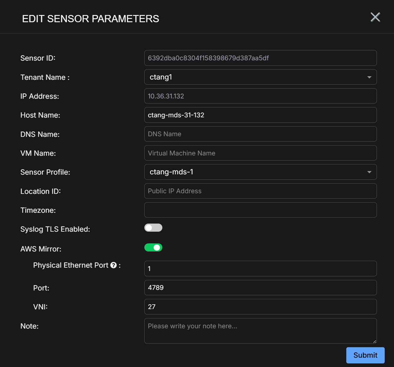
-
Click Submit. The parameters are immediately updated.
Verifying Traffic
After the Modular Sensor receives mirrored traffic, verify that the Stellar Cyber Platform is generating Interflow records and related detections.
- Confirm that the sensor status is healthy.
- Search for Interflow records associated with the source virtual machine private IP address.
- Use Investigate and Search to confirm that packet-derived metadata is present.
Troubleshooting
|
Error or Symptom |
Cause |
Resolution |
|---|---|---|
|
|
Azure VTAP is not supported in the selected region |
Use a supported region. |
|
|
Microsoft approval is not complete |
Wait for approval or contact Microsoft Support. |
|
|
Azure Policy blocks the target region |
Update the Allowed Locations policy. |
|
|
The destination reference uses the wrong Azure resource type |
Use the IP configuration ID ending in |
|
No traffic on collector port in the same virtual network |
The collector-side Network Security Group blocks UDP 4789 |
Allow inbound UDP 4789 from |
|
No traffic on collector port in different virtual networks |
Collector-side filtering blocks UDP 4789, or peering is not connected |
Allow inbound UDP 4789 from the source virtual network CIDR and verify peering status. |
|
No traffic on collector port |
Azure VTAP is not attached to the source NIC |
Verify that the VTAP configuration exists on the source NIC. |
|
Internal load balancer backend is unhealthy |
The TCP 22 health probe fails on Modular Sensor NIC 2 |
Allow TCP 22 from the |
|
|
Regional vCPU quota is too low |
Use a smaller supported VM size or request a quota increase. |
|
|
Wrong flag in |
Use |
|
Multi-NIC VM fails in PowerShell |
Missing |
Ensure |
|
Script login fails in Cloud Shell |
Cloud Shell session expired |
Refresh the Cloud Shell session and re-run. |
|
Source traffic is visible even though the source Network Security Group blocks it |
This is expected behavior for Azure VTAP |
Check the collector-side Network Security Group if traffic does not reach |
