Installing a Modular Sensor in OCI
This topic describes how to install a Modular Sensor in an Oracle Cloud Infrastructure (OCI) environment. Refer to the following sections for details:
Use our example as a guideline, as you might be using a different software version.
Stellar Cyber does not support the installation of third-party software on its virtual or physical device sensors.
About Modular Sensors
Sensors provide the data gathering foundation for Stellar Cyber's OpenXDR platform, gathering the right data with context. Modular sensors are purpose-built Stellar Cyber sensors that include both the host and the Stellar Cyber monitoring software. They are provided as both physical devices (Photon sensors) and virtual machine images for different target environments.
Previous releases provided a variety of different types of device sensors, including Network, Security, and Modular. Going forward, the only type of device sensor is Modular. You can use the Modular Sensor Profile to enable whatever sensor features you like, creating the same functionality provided by the different sensor types in previous releases.
A modular sensor lets you easily add the features you like to your sensor. This helps simplify your deployment and lets you manage the VM requirements for the sensors based on the modular features they use.
Modular Sensors always include log ingestion. From there, you can enable different features as part of your modular sensor profile:
-
Enable the Network Traffic feature to monitor the virtual environment, the physical environment if connected to the span port of a physical switch, or the LAN segment via a mirror port on a switch. The sensor monitors network and server response times and can identify applications.
The sensor converts that information to metadata and forwards it to the DP as Interflow. The DP can then provide security, DDoS, and breach attempt detections.
-
Enable the Sandbox and IDS features to improve your security posture:
- Sandbox lets you detect malware in files and network traffic through Stellar Cyber's integrated cloud service and also provides anti-virus services.
- IDS lets you detect intrusion attempts using both files and network traffic.
Keep in mind that VM resource requirements increase as you add more features to the Modular Sensor Profile. Refer to Modular Sensor Specifications for details on the resources required to run different combinations of features in a Modular Sensor Profile, as well as how to use the show module and show module request CLI commands to compare provisioned resources against those required to run specific feature combinations. Stellar Cyber only enables a Modular Sensor Profile on a sensor if the host VM's resources can support it.
Site Preparation
Refer to Modular Sensor Specifications for details on the resources required to run different combinations of features in a Modular Sensor Profile. Provision your modular sensor according to the features that you plan on enabling.
You will also need to open firewall ports for the features you plan on enabling in the Modular Sensor Profile for this sensor.
Obtaining the Installation File
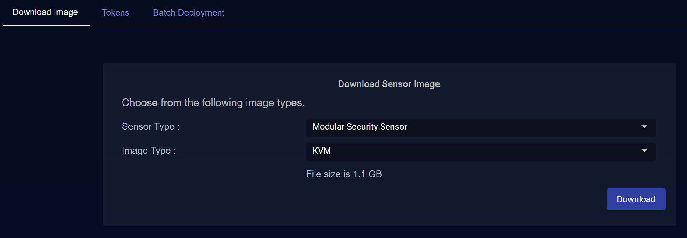
You download the installation file for the Modular Sensor for OCI from the Download Images tab in the System | Deployment | Sensor Installation page. Use the following procedure:
Only users with the Deployment | Sensor Installation | Sensor Image Download privilege assigned to their profile in the System | Role-Based Access Privileges interface can download images.
-
Navigate to the System | Deployment | Sensor Installation page.
-
Set the Sensor Type dropdown to Modular Security Sensor.
-
Set the Image Type to KVM.
The same qcow2 installation file used for KVM can also be used for OCI.
The display updates to show you the size of the file to be downloaded.
-
Click the Download button. The system downloads the installation file (aella-modular-ds-5.x.x.qcow2.zip) along with its corresponding SHA-1 hash file.
-
Unzip the installation file's contents (virt_deploy_modular_ds.sh and aella-modular-ds-5.x.x.qcow2).
You will upload the aella-modular-ds-5.x.x.qcow2 image file to OCI in the next section.
Installing the Modular Sensor Image
This section describes how to install the Modular Sensor image in OCI:
-
Log in to Oracle Cloud Console at https://cloud.oracle.com/.
-
Click the main menu icon at the top left of the Oracle Cloud Console.

-
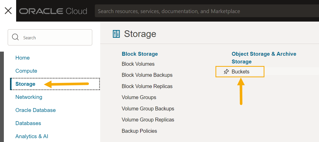
If you do not already have a bucket for the Modular Sensor, navigate to Storage | Buckets.
-
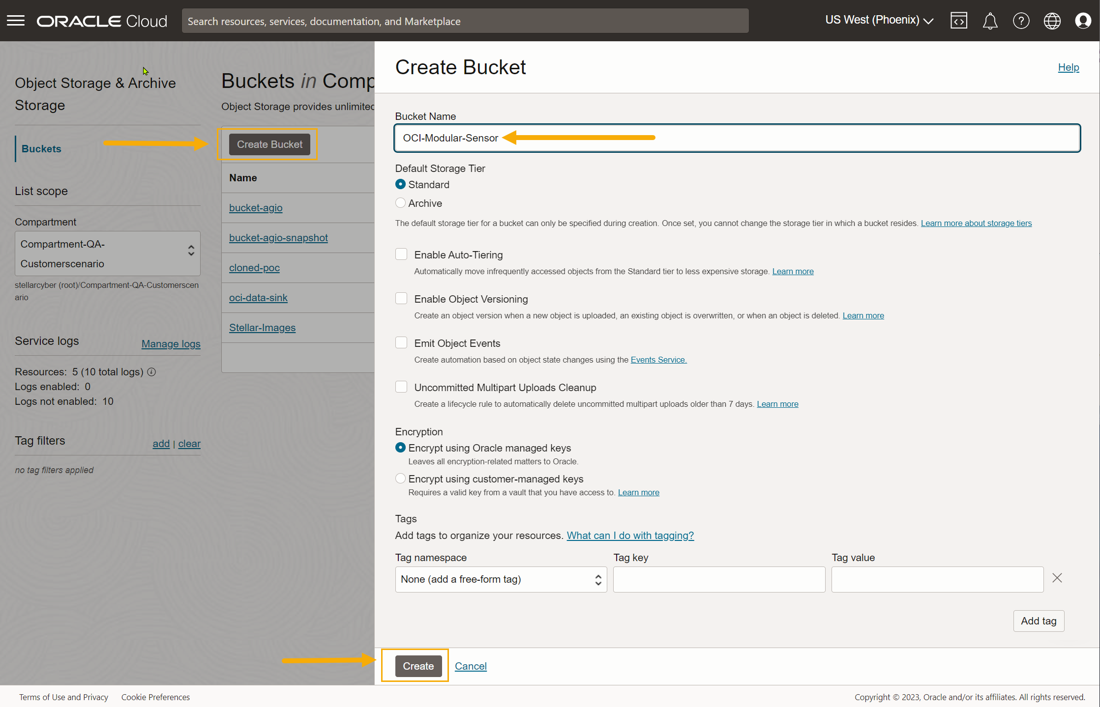
Click Create Bucket to add a new bucket. Select the Standard storage tier, supply a name, and click Create to add the bucket to your account.
-
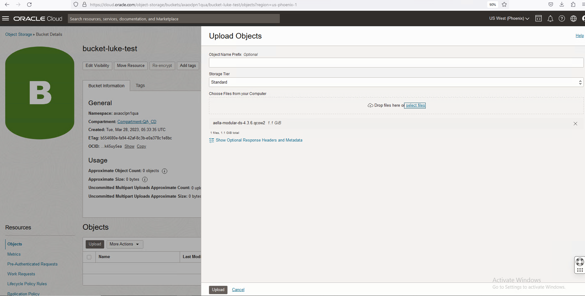
Click the entry for the bucket you just created. Then, use the Upload button to upload the aella-modular-ds-5.0.x.qcow2 image you downloaded in Obtaining the Installation File. The Choose Files from your Computer field lets you either drag and drop the file or select the file in a standard Browse dialog box.
-
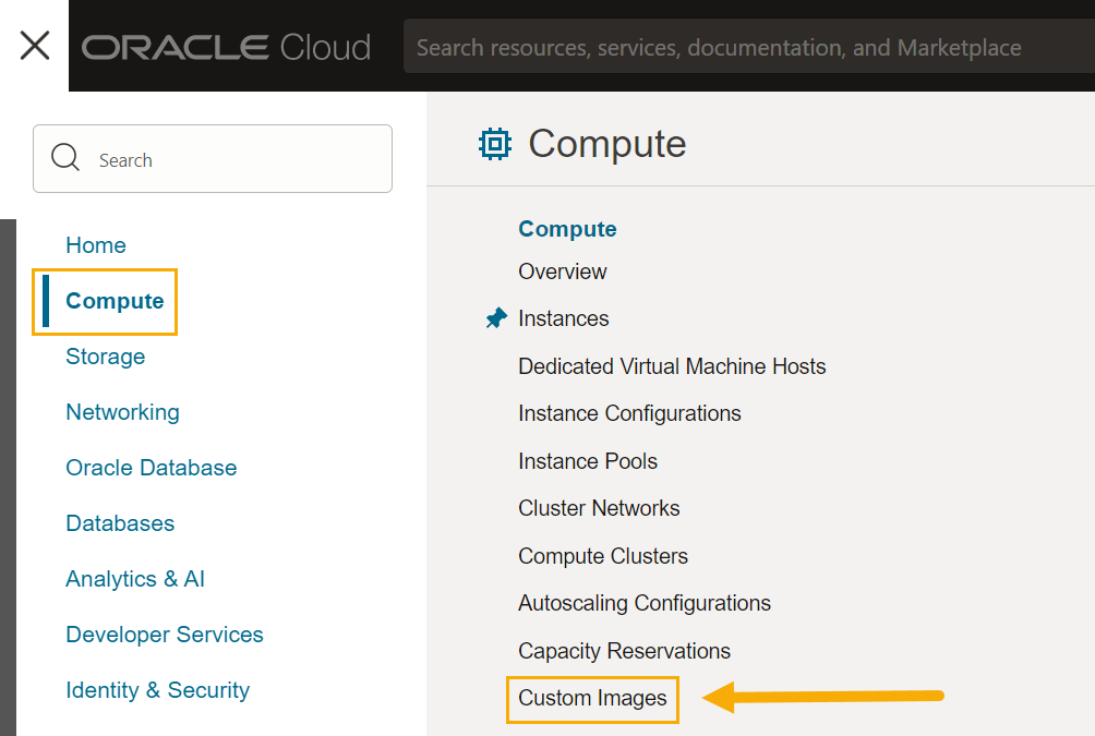
Click the main menu icon and navigate to Compute | Custom Images.
-
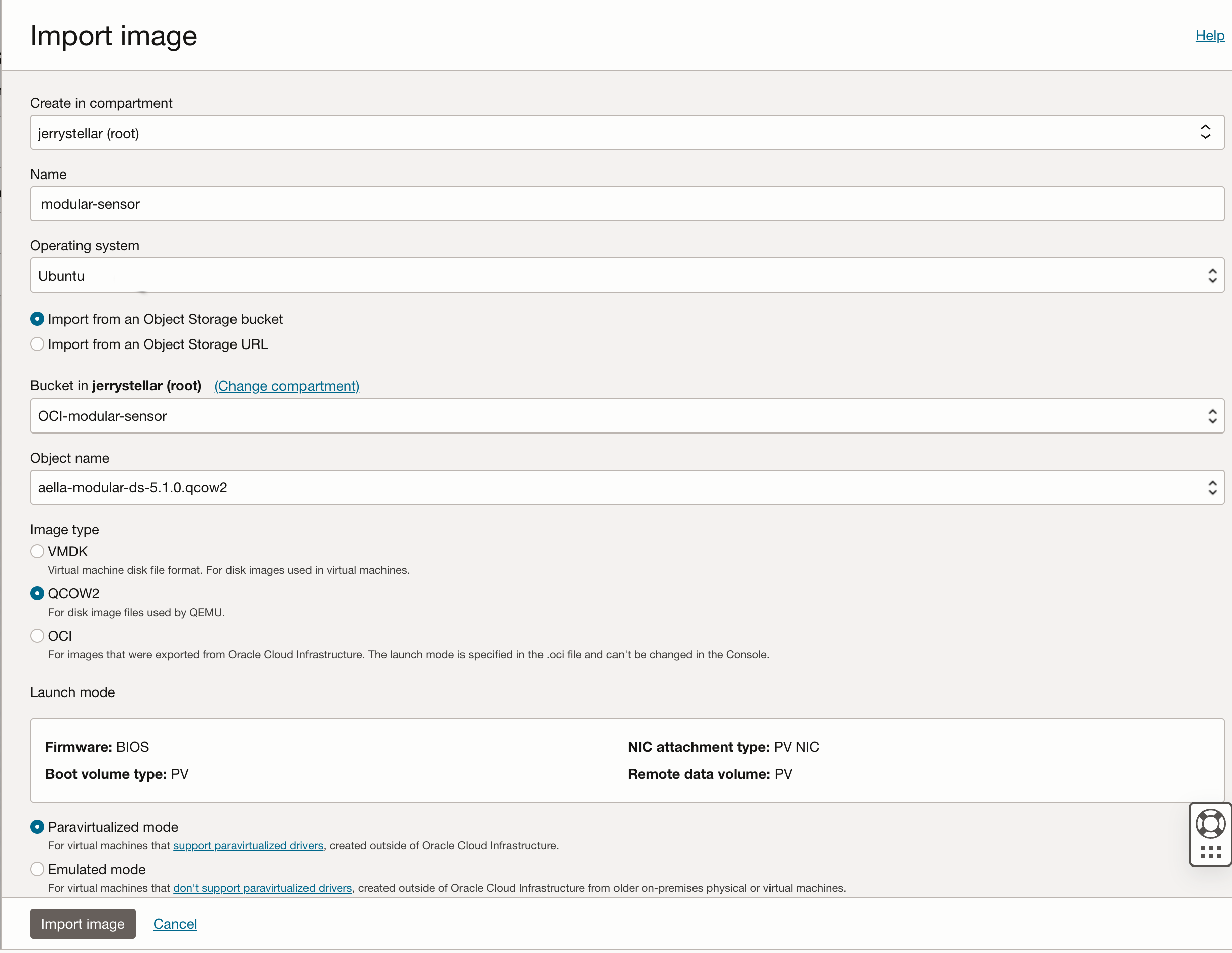
Click the Import image button and fill out the Import image dialog box as follows:
-
Supply a Name.
-
Use the Bucket field to select the bucket where you uploaded the image at the start of this procedure.
-
Use the Object name field to select the aella-modular-ds-5.0.x.qcow2 image.
-
Set the Operating system to Ubuntu.
-
Set the Image type field to QCOW2
-
Leave Launch mode set to Paravirtualized mode.
The figure below provides an example of the settings:
-
-
When you have finished configuring the settings in the Import image dialog box, click the Import image button to start the import process.
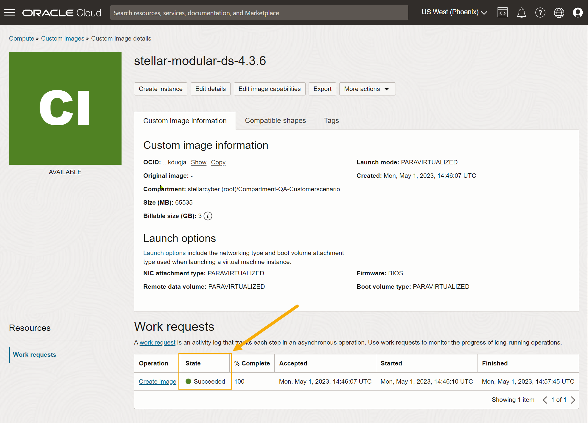
The Custom image details page appears for the image while it imports. When the image has finished importing, it appears with a value of Succeededin the State column, as shown below.
-
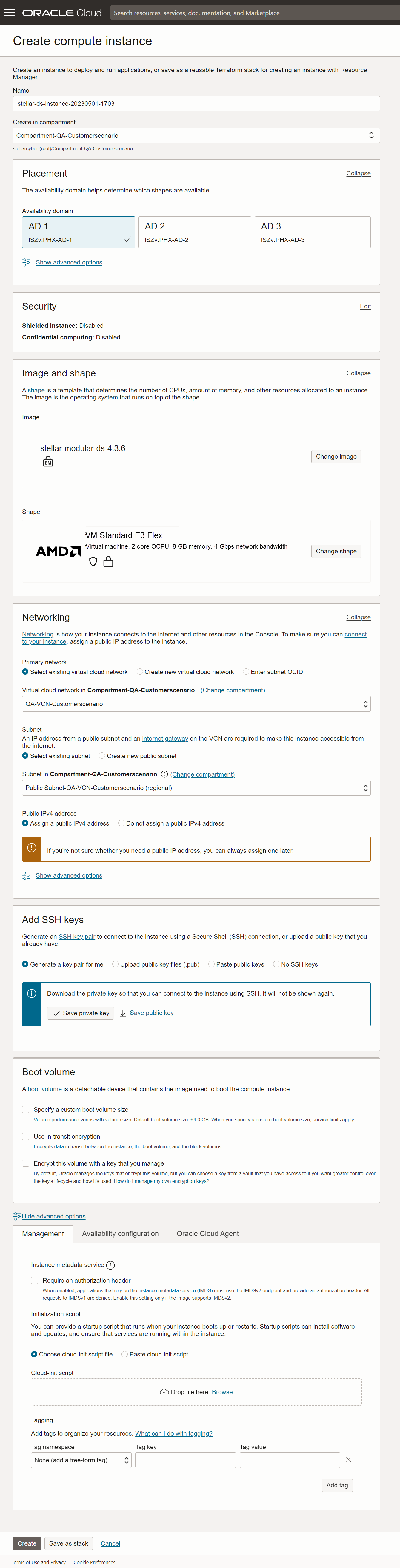
Once the image has finished importing, click the Create instance command to create a new instance based on the image. Set the options in the Create compute instance dialog box as follows:
-
Supply an easily identifiable Name for the new instance.
-
Choose the compartment and availability domain for the new instance. Make sure you choose the availability domain where you want to receive traffic.
-
Leave Image set to stellar-modular-ds-5.0.x.
-
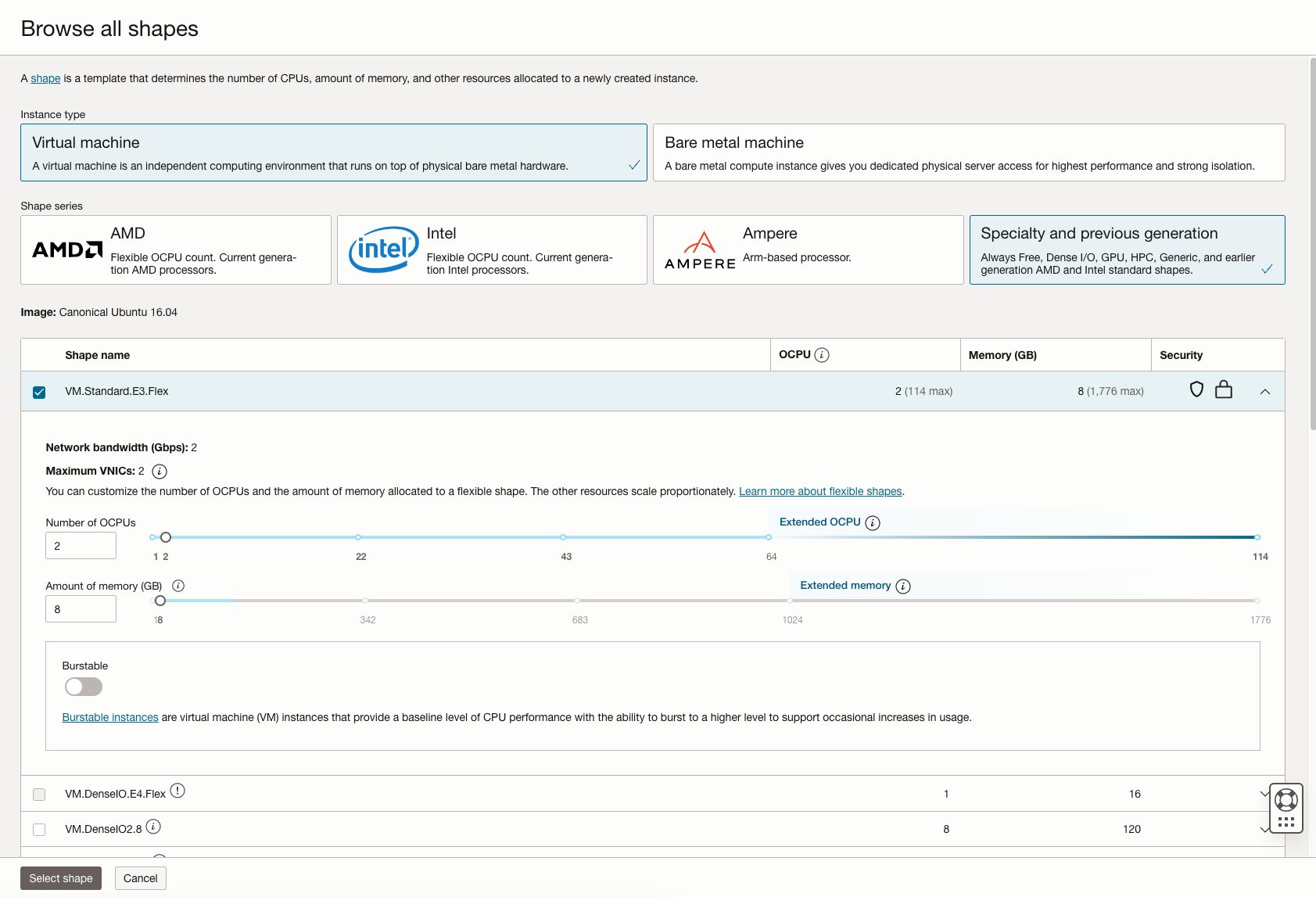
The Shape field lets you select from VMs with a variety of different provisioning. Choose a shape that corresponds to the resources required by the features to be enabled in this sensor's Sensor Profile.
You can customize the CPUs and memory for many of the available shapes by clicking Change shape and adjusting as necessary. For example, we know we want to enable the Log Collector, Log Forward, and Network Traffic features, so we've chosen the VM.Standard.E3.Flex shape and adjusted its settings to the minimum values of 2 OCPUs and 8 GB of memory.
-
Use the Networking options to select the Primary network and Subnet for the sensor's management interface.
-
In most cases, you'll want to Assign a public IPv4 address to the management interface. This lets you manage the sensor from a DP located outside the OCI public cloud.
-
Use the Add SSH keys options to decide how you want to connect to the sensor using SSH. We are letting OCI generate a key pair for us and saving the resulting private key locally.
-
You can leave the other options set to their defaults.
The figure below shows our settings so far.
-
-
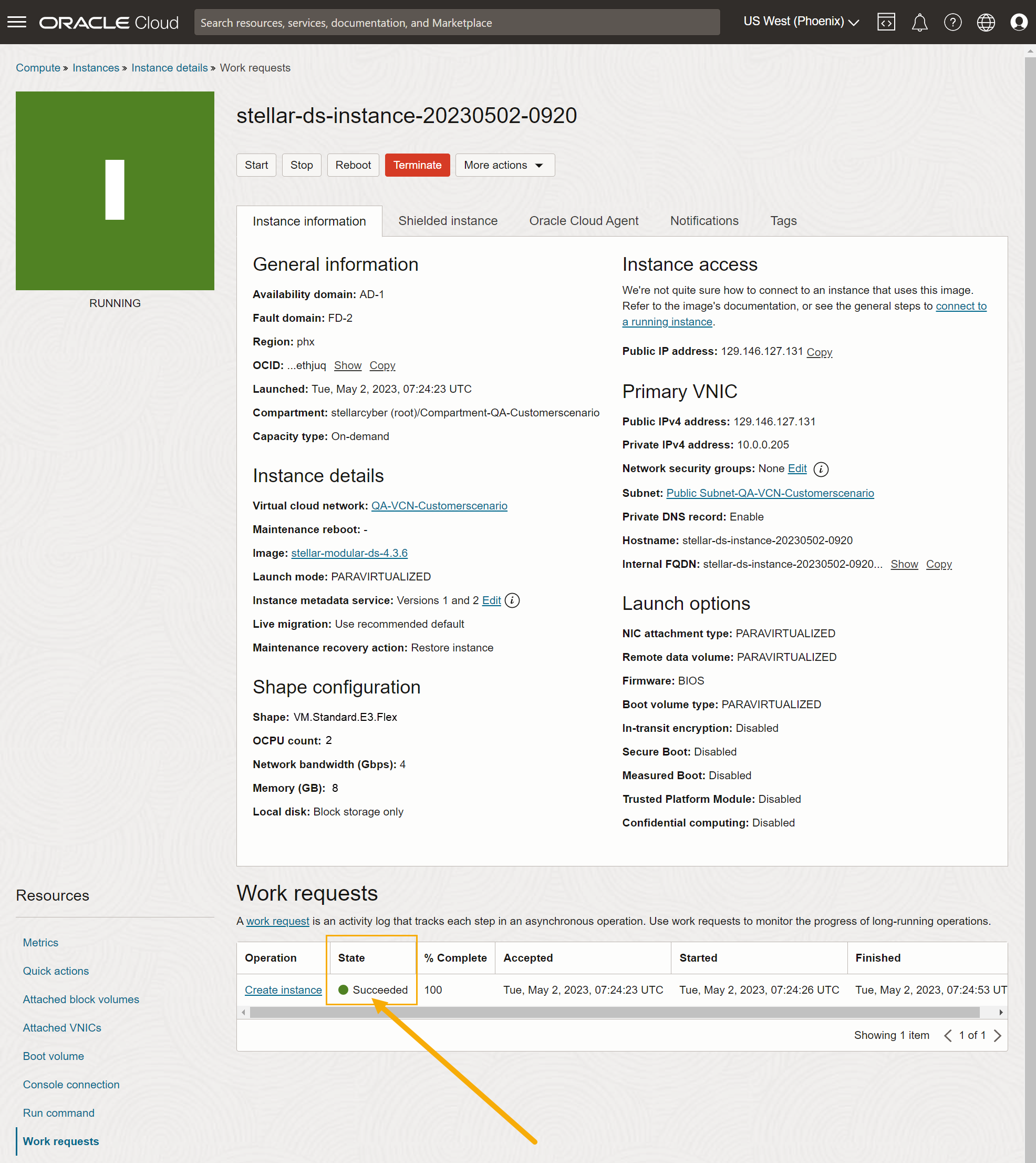
When you are satisfied with your settings, click Create to create the instance.
OCI begins to create the instance, tracking its progress in the Instance details | Work requests display. Once the State shown in the Work requests table shows Succeeded, as illustrated in the example below, you are ready to add a second VNIC to be used as a monitoring interface. See below.
Adding a Second Monitoring Interface
The next step is to add the following resources to the Modular Sensor virtual machine:
-
Second network adapter to be used as a monitor interface. This adapter will eventually monitor traffic from the VTAP we configure in Configuring a Static IP Address (Optional).
-
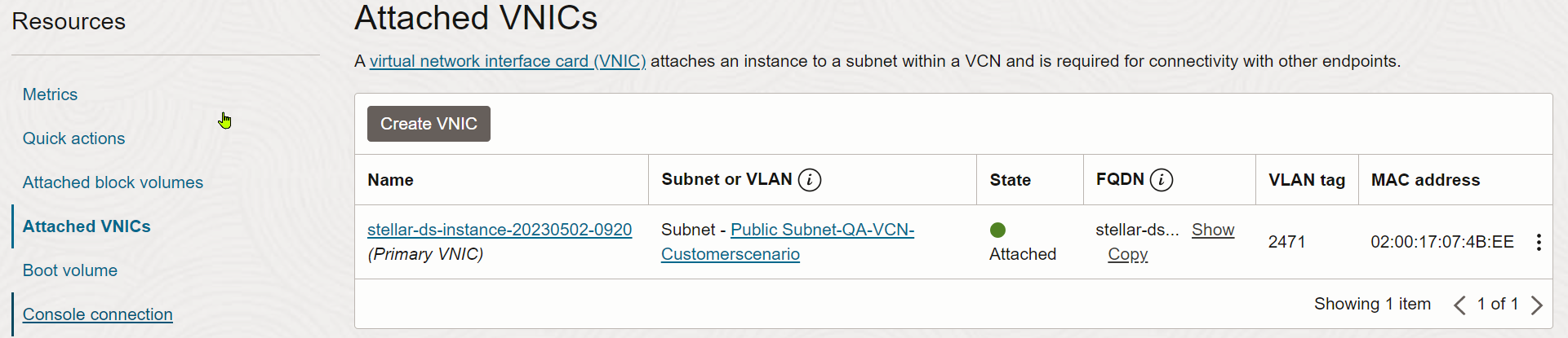
You should still be in the Instance Details page for the Modular Sensor virtual machine. Click the Attached VNICs link in the Resources menu at the left of the page.
The Attached VNICs table appears. At this point, only the primary VNIC is attached to the VM. This is the management interface for the sensor.
-
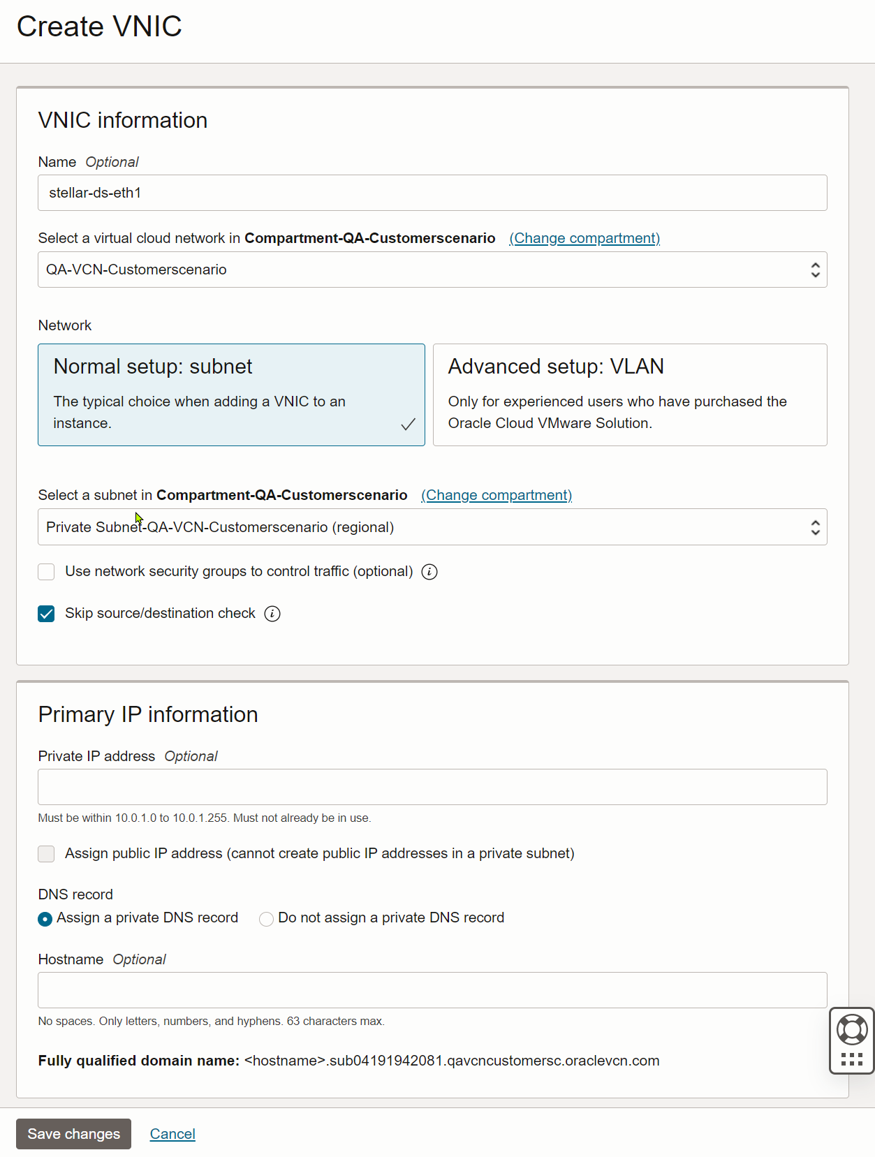
Click the Create VNIC button at the top of the table. Then, supply the following information in the Create VNIC page:
-
Supply an optional Name.
-
Select the network and subnet to which the monitoring interface should be connected. Choose a network/subnet accessible to the VTAP you will use as the source of network traffic.
-
Because we are using a VTAP in OCI to feed traffic to this monitoring interface, we do not need a public IP address. We'll let OCI assign a private IP address.
Here's how our settings look so far:
-
-
Click Save Changes to add the new VNIC to the sensor VM.
The Attached VNICs table updates to show the newly attached monitoring interface:
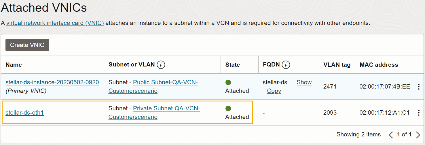
-
Click the entry for the second VNIC you just created.
-
Locate and record the second VNIC's private IP address. You'll need this when you add the sensor to the DP and set up the VTAP to direct traffic to it. For example:
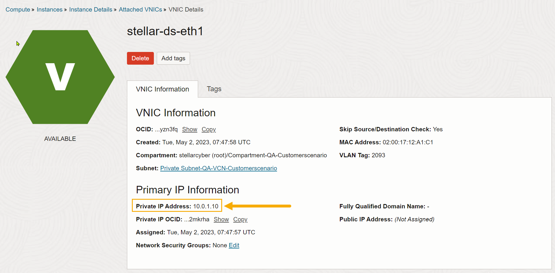
Stellar Cyber does not support reconfiguration of the monitoring interface's IP configuration using the sensor's built-in set data-port-ip command. Use OCI's native services for IP configuration instead.
Applying a Token to the Installed Sensor
The next step is to obtain and apply the token used to authorize and configure the installed sensor.
Obtaining a Token for the Installation
Tokens are required to authorize and configure the installation of a sensor image downloaded from the DP in the System | Deployment | Sensor Installation page. Tokens point the installed sensor to the correct DP, assign the specified tenant, and authorize the sensor installation.
Use the following procedure to obtain a token in the Tokens tab:
-
Navigate to the System | Deployment | Sensor Installation page and click on the Tokens tab.
-
If a token already exists for the target tenant for the sensor installation, you can either use the Copy button to copy it to the clipboard or use the Download button to download it as a file.
-
Copy the token if you plan on applying it by pasting it into a
set token string <token>command in the CLI. -
Download the token as a file if you plan on hosting the file on an HTTP server and referring to it in a
set token url <token url>command.
Refer to Assigning Tokens for a summary of the different ways in which tokens can be applied to a sensor installation.
-
-
If there is not already an unexpired token for the target tenant, click the Generate button.
The Generate Installation Token dialog appears:
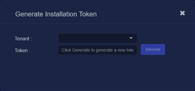
-
Select the tenant for the token from the Tenant dropdown. This is the tenant to which all sensors authorized with this token will be automatically assigned. The dropdown lists all tenants configured for your organization in the System | Tenants page.
-
Click the Generate button.
The system generates the token and displays its contents in the Token field. The dialog also updates to display the expiration date for the token, as illustrated below.
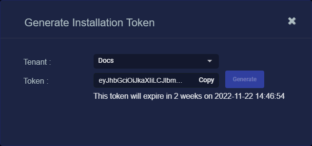
-
You can use the Copy button to copy the token to the clipboard immediately, or simply close the dialog and retrieve the token from the Tokens tab later on.
Applying the Token to the Sensor
Tokens are required to complete the installation of a sensor image downloaded from the DP in the Download Image tab.
You apply tokens to sensors as the last step in the overall installation procedure:
- Log in to your new Sensor. The default username/password is aella/changeme. You are immediately prompted to change the password.
-
Apply the token to the installed sensor from the sensor CLI with the
set tokencommand using one of the options in the table below:You only need to use one of the options in the table below. These are just two different ways to do the same thing – apply the token.
Option 1. Copy and Paste the Token String
Copy the token string from the Tokens tab and paste it into the CLI command. The syntax is as follows:
set token string <pasted string>Option 2. Host the Token on an HTTP Server
Download the token as a file from the Tokens tab, upload it to an HTTP server, and reference it in the
set tokencommand. The syntax is as follows:set token url http://<url to token>You can also use an HTTPS server. In that case, the specified URL must also include the username and password for the server using the following syntax:
set token url https://<user:password>@URL> -
The CLI reports that the Sensor token is successfully set.
If you receive an error message instead, it's possible that the token has expired. Refer to the Tokens tab to see the expiration date. If you are using the File technique, it's also possible that an extra space or line may have crept into your text file – check the file to make sure it includes only the token text.
-
Wait a minute or so. Then, verify that the token was successfully applied using any combination of the following techniques:
-
Check the System | Sensors tab in the user interface to see that the sensor has registered itself successfully.
-
Verify that the
show systemcommand shows all services as running. -
Verify that the
show receivercommand displays a receiver. -
Verify that the
show jsoncommand reports some data sent in theBYTE_SENTcolumn.
-
Configuring a Static IP Address (Optional)
By default, the sensor uses DHCP for the management port's IP address. For ease of troubleshooting, however, Stellar Cyber recommends that you reconfigure the management port to use a static IP address. The procedure is as follows:
- Log in to your sensor. The default username/password is aella/changeme, but you changed this when you applied the token in the previous section.
-
You can set IP parameters manually using commands similar to the following (substitute your own IP parameters for the ones shown in bold below):
set interface management ip 192.168.14.100/255.255.255.0
set interface management gateway 192.168.14.1
set interface management dns 8.8.8.8
-
Verify the IP settings with the
show interfacescommand. - Log out with the
quitcommand.
Configuring a VTAP in OCI
There are many ways to configure traffic acquisition in OCI. In our example, we'll use the following technique:
-
We'll create a VTAP in OCI that mirrors traffic on a specific interface.
-
The mirrored traffic is sent to a Load Balancer in OCI that we'll also create.
-
One of the targets of the Load Balancer is the monitoring interface (second VNIC) of the Modular Sensor.
-
Traffic sent from the Load Balancer to the monitoring interface is encapsulated in VXLAN packets, so we'll set up the AWS Mirror feature in Stellar Cyber so that the VXLAN traffic is parsed and the interior packets are read correctly by the sensor.
The procedures below show how to set up a deployment like this.
Create the Load Balancer and Point it at the Sensor's Monitoring Interface
-
Click the main menu icon at the top left of the Oracle Cloud Console and select the Networking | Virtual cloud networks option.
-
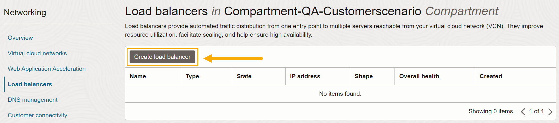
Click the Load balancers entry in the Networking menu at the left of the page. Then, click the Create load balancer button to add a new load balancer.
-
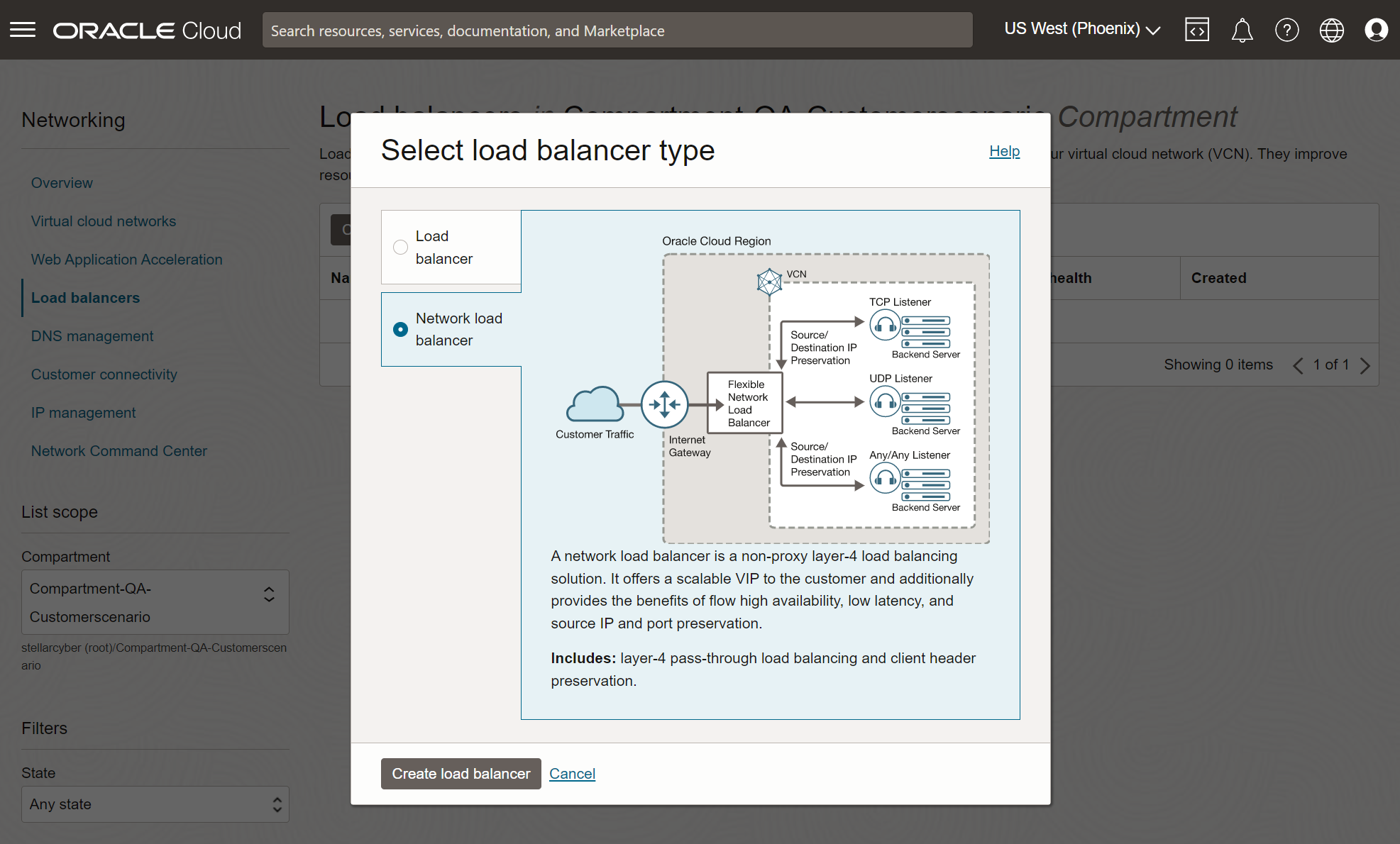
Choose the Network load balancer option.
-
Click Create load balancer.
-
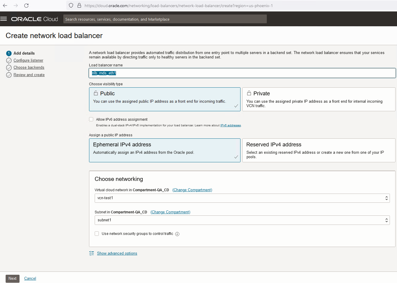
Supply a name for the load balancer and select a network and subnet. Make sure you select a network and subnet accessible to the modular sensor's monitoring interface. For example:
-
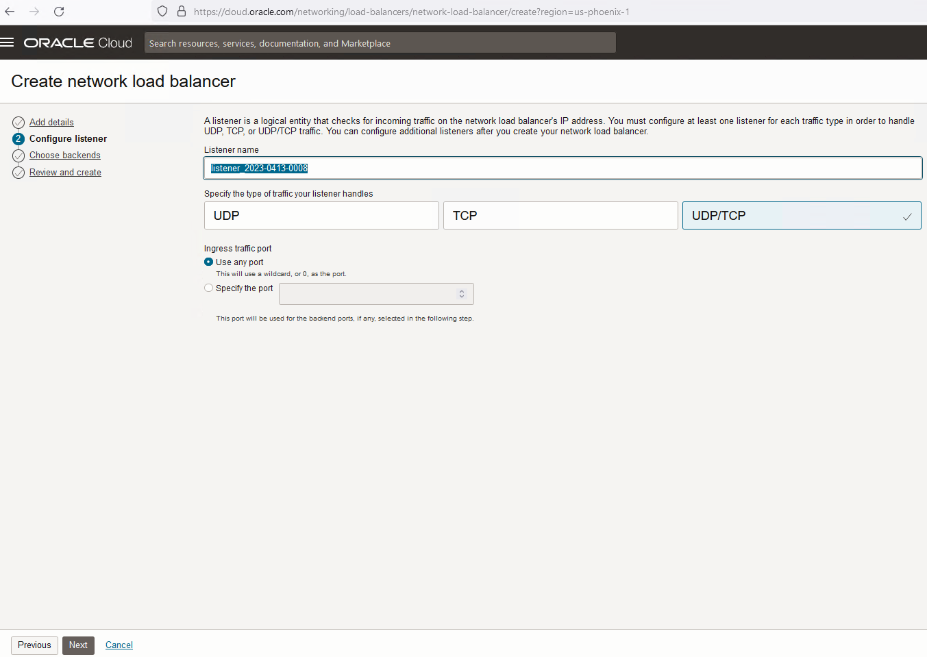
Click Next and configure a logical listener for the load balancer. Set the traffic type to UDP/TCP and leave Ingress traffic port set to Use any port. For example:
-
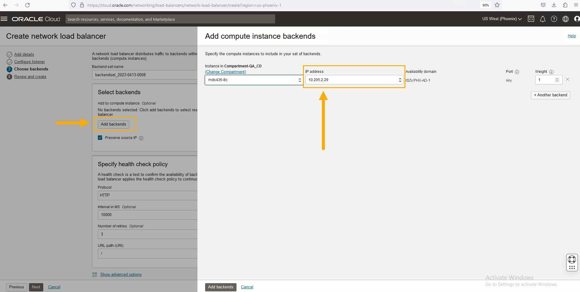
Click Next to display the Choose backends screen. This is where we'll point the load balancer to the modular sensor VM's monitoring interface.
-
Click the Add backends button and use the Compartment and IP address fields to select the monitoring interface of the modular sensor that we recorded during the installation of the sensor in the previous sections. For example:
-
Click Add backends and the select the new backend's entry in the Select backends list.
-
Health checks are mandatory for backends. Specify a port for the backend and click Next.
-
Click Create network load balancer to finish the creation of the load balancer.
Create the VTAP and Point it at the Load Balancer
-
You should still be in OCI's Networking interface. Click the Network Command Center in the menu at the left of the page.
-
Click the Traffic monitoring | VTAPs entry.
-
Click the Create VTAP button.
-
Supply a name for the VTAP.
-
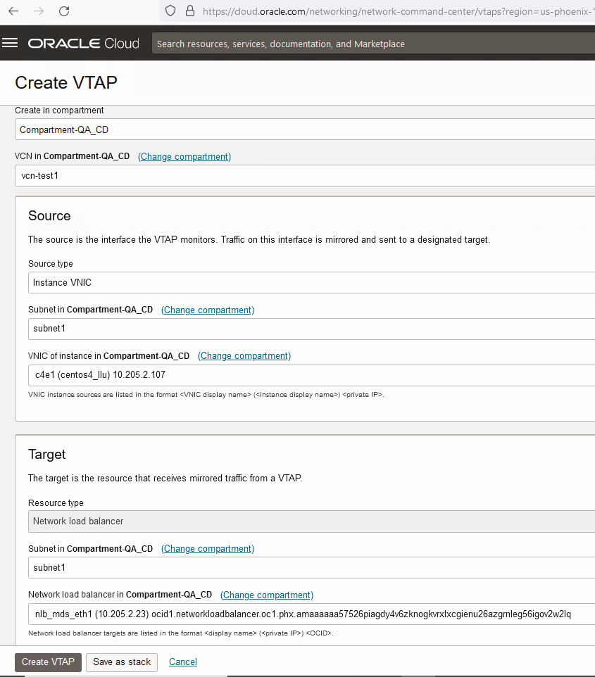
Use the Source fields to select the traffic the VTAP monitors. In this example, we're tapping the traffic on a specific instance's VNIC.
-
Use the Target fields to select where traffic monitored by the VTAP should be mirrored. The destination is the Network load balancer we created in the previous section.
-
You can configure optional Capture filters to limit the traffic mirrored by the VTAP.
Here's our sample VTAP configured to send traffic from a specified VNIC to our load balancer:
-
Click Create VTAP to add the VTAP and start tapping traffic to the load balancer.
Enable the AWS Mirror Feature
Traffic sent from the load balancer to the sensor's monitoring interface is encapsulated in VXLAN packets. You can configure the sensor to parse the VXLAN packets and read the encapsulated packets by enabling the AWS Mirror feature on the sensor. Use the following procedure:
Although the feature is called AWS Mirror, it can be used to enable VXLAN parsing on a sensor interface regardless of the actual source.
-
Log in to Stellar Cyber.
-
Go to System | Collection | Sensors. The Sensor List is displayed.
-
Click for the sensor used as the destination for the load balancer in OCI. The Edit Data Sensor Parameters window is displayed.
-
Enable AWS Mirror. Additional fields are displayed.
-
Set Physical Ethernet Port to 1. You can find this by using the
show vtepcommand on the sensor. -
Leave Port set to its default value of 4789.
-
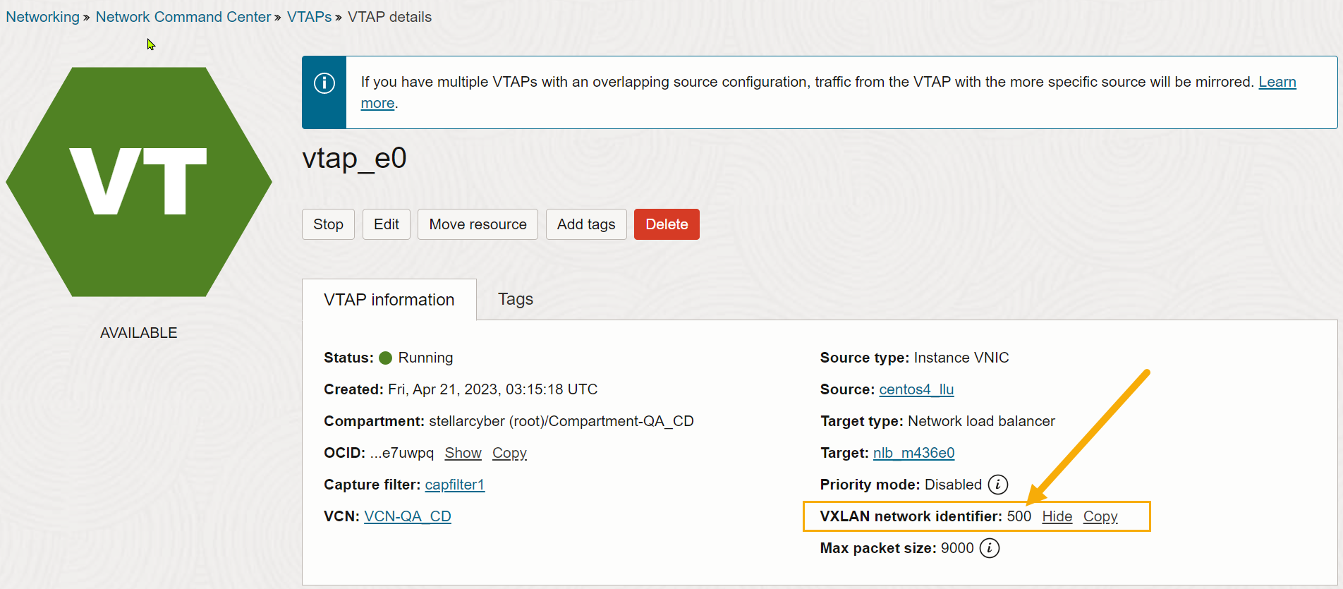
Set VNI to the VXLAN ID for your VTAP in OCI. You can find this in the VTAP details screen for your VTAP. For example:
-
Click Submit. The parameters are immediately updated.
