Installing a Modular, Network, or Security Sensor in Hyper-V
A network sensor monitors the virtual environment, the physical environment if connected to the span port of a physical switch, or the LAN segment via a mirror port on a switch. The sensor monitors network and server response times and can identify applications.
The network sensor converts that information to metadata and forwards it to the DP as Interflow. The DP can then provide security, DDoS, and breach attempt detections.
A security sensor operates as a network sensor and adds:
- sandbox
- anti-virus
- IDS
You can also tunnel traffic over VXLAN from an agent sensor, network sensor, or container sensor to the security sensor so it can inspect those environments.
A modular sensor lets you easily add the features you like to your sensor. This helps simplify your deployment and lets you manage the VM requirements for the sensors based on the modular features they use.
You can install a modular, network, or security sensor on a Microsoft Hyper-V virtual machine.
Site Preparation
This process requires a Microsoft Hyper-V environment on a Windows server. Windows Server 2016 is the tested version.
Click to see the minimum system requirements for installing a modular, network, or security sensor.
You will need:
- Server switch with a physical network interface that supports promiscuous mode
- One IP address with access to a default gateway
- A Stellar Cyber license that can be applied to the sensor
- Open firewall ports for a network sensor
- Open firewall ports for a security sensor
- Open firewall ports for log ingestion
Downloading Images
You can download the images for modular, network, and security sensors using the links below.
Installation links point to the most recent release. To download a different version, simply substitute the version you want for the version specified in the link.
-
Download the modular sensor image from the Stellar Cyber production server at the following URL:
https://acps.stellarcyber.ai/release/4.3.7/datasensor/aella-modular-ds-4.3.7.vhdx
-
Download the network sensor image from the Stellar Cyber production server at the following URL:
https://acps.stellarcyber.ai/release/4.3.7/datasensor/aella-device-ds-4.3.7.vhdx
-
Download the security sensor image from the Stellar Cyber production server at the following URL:
https://acps.stellarcyber.ai/release/4.3.7/datasensor/aella-device-sds-4.3.7.vhdx
Contact Stellar Cyber support (support@stellarcyber.ai) for login credentials and a one-time password (also known as a License Key).
Our example assumes that the file has been downloaded into the local C:\Users\Public\Documents\Hyper-V\Virtual hard disks\ folder.
Creating A Virtual Switch
The first step is to create a virtual switch through which the VM will communicate.
Use our example as a guideline, as you might be using a different software version.
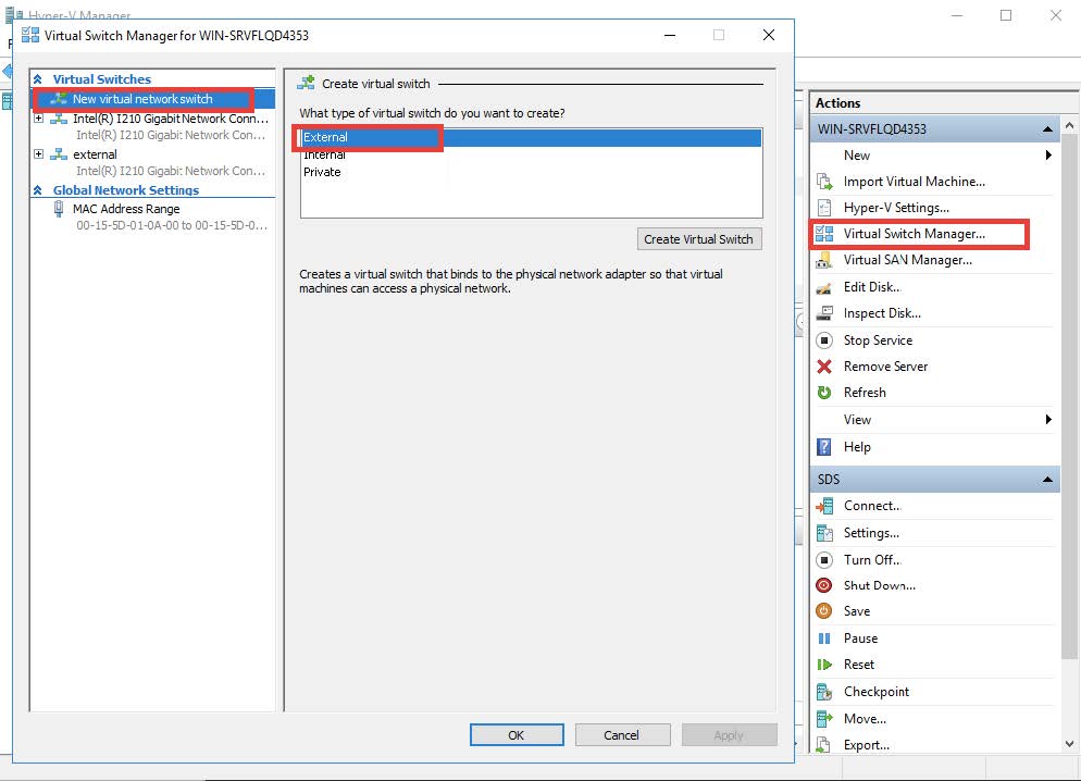
Start the Hyper-V manager and open the Virtual Switch Manager from the right-hand sidebar. Select Create Virtual Switch then choose External Network. The resulting display is shown in the following image.
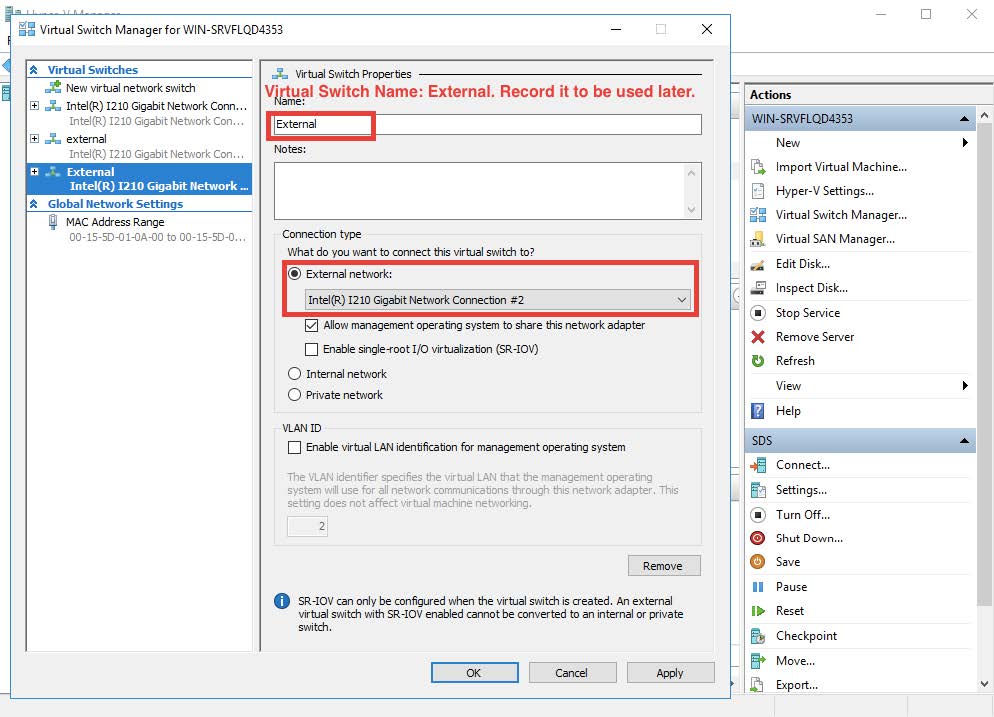
The next step is to select the physical network port that is to be used to connect to the outside world. The result will look similar to the sample in the following image.
Setting Promiscuous Mode
Promiscuous mode is used so that the sensor can monitor all traffic. This setting is not supported via the user interface so the following commands must be used via the PowerShell.
In this example the name of the switch is "External." This must be modified for the value actually used.
C:\Users\Administrator> $a = Get-VMSystemSwitchExtensionPortFeature -FeatureId 776e0ba7-94a1-41c8-8f28-951f524251b5
				C:\Users\Administrator> $a.SettingData.MonitorMode = 2
				C:\Users\Administrator> add-VMSwitchExtensionPortFeature -ExternalPort -SwitchName <name of the switch> -VMSwitchExtensionFeature $a
Creating a New VM
-
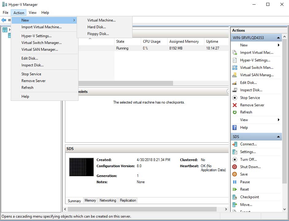
Return to the Hyper-V manager and select Action | New | Virtual Machine....

-
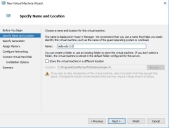
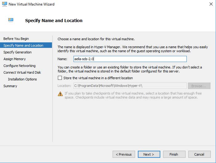
Specify a name for the new security sensor. This can be any legal VM name but it is recommended to adopt a site convention so that the name identifies the type of sensor. The screen will look similar to the following image.
-
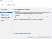
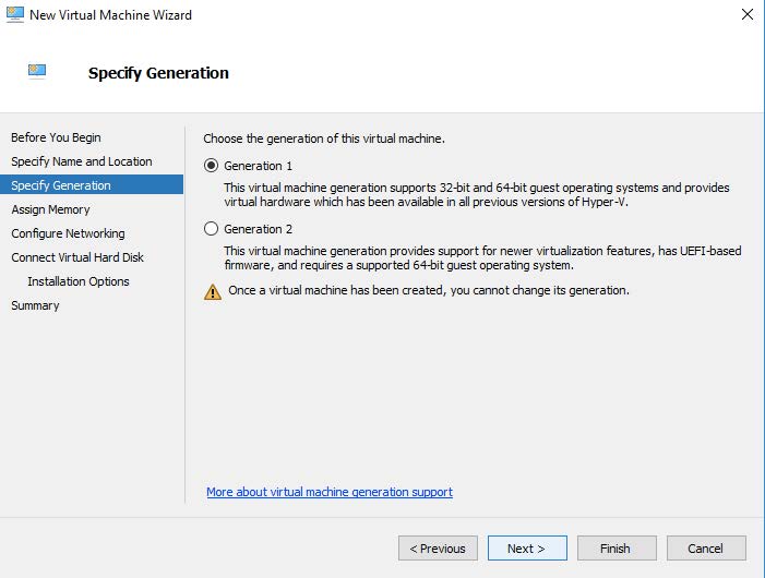
Enter the Generation parameter. The guest Operating System is a 64-bit OS so "Generation 1" is a good choice as shown in the following image.
-
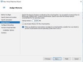
Next, assign memory according to the sensor's expected workload, as stated in Virtual Appliance Sizing Specifications.
-
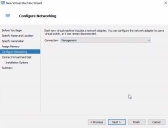
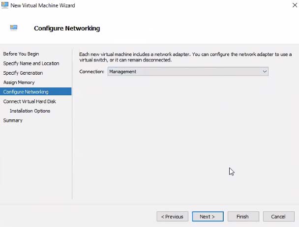
Configure the Management network interface. You can either enter a static IP or configure using a DHCP server. This is the interface that will be used for the sensor to send its Interflow data records to the data processor. The networking is selected as in the following image.
-
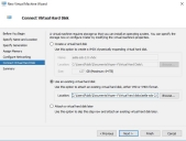
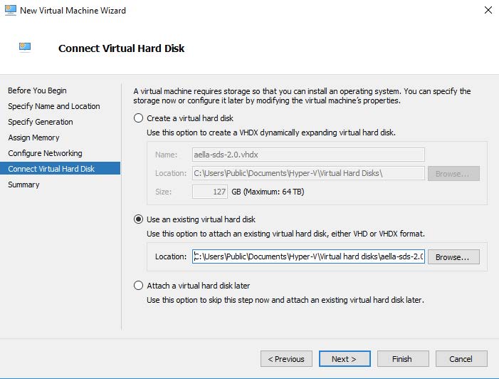
Connect the Virtual Disk image that was downloaded in the site preparation mentioned above. In the dialog box use the Use existing option as shown in the following image. If the image was placed in a different location adjust the Location field appropriately.
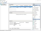
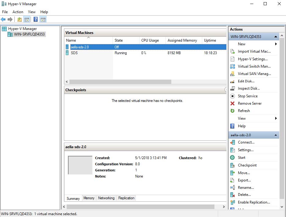
At this point the creation of the VM is complete and it should appear in the Hyper-V Manager screen in a manner similar to the following image.

Changing the Processor Setting
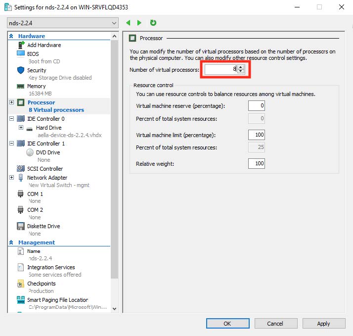
Before activating the VM, it needs to have the proper number of CPU cores allocated to it. Select the VM in the list and click Settings | Processor menu options. In the resulting dialog box, change the number of processors according to the sensor's expected workload, as stated in Virtual Appliance Sizing Specifications.
Ensure that Processor Compatibility Mode is Disabled 
Stellar Cyber sensors deployed in Hyper-V must have the processor compatibility feature disabled to ensure that the SSSE3 instruction set can be used and that aella_flow runs properly. Although the sensor VM starts and appears to run correctly with processor compatibility enabled, stability issues will eventually occur due to high CPU usage.
You can verify that processor compatibility mode is disabled in the same dialog box where you just assigned CPU cores:
-
Expand the Processor entry in the left pane of the Settings dialog box.
-
Click on the Compatibility entry.
-
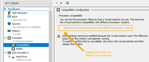
Ensure that Migrate to a physical computer with a different processor is disabled and click OK.
The image below shows you the option that must be disabled for Stellar Cyber sensors:

Adding an Interface
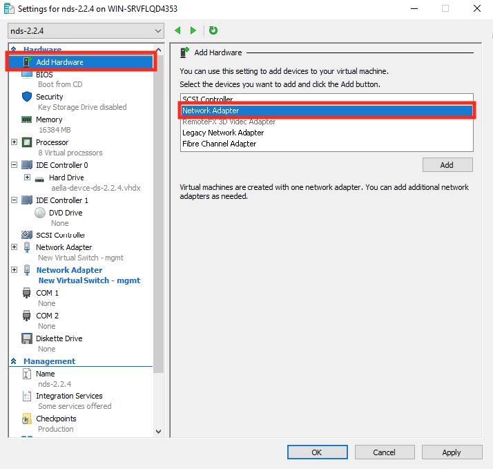
The aggregator requires a connection to the virtual switch that we created in the first steps. Click Add Hardware | Network Adapter as shown in the following image. Note that you can only add a network adapter to the VM while it is powered off.
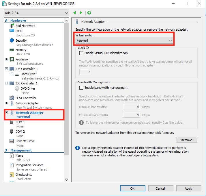
After the interface is created, select the virtual switch that was created in the first steps of this procedure.
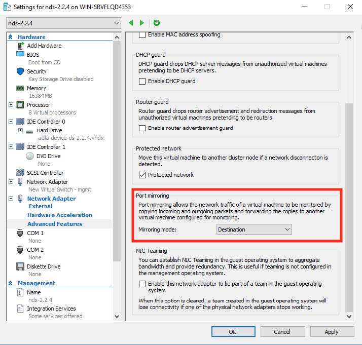
Expand the associated network adapter and click Advanced Features. Set the mirroring mode of the aggregator to Destination. This is shown in the following image.
When you have finished adding the interface, power the VM on.
Connecting the Sensor to the DP
To connect to the DP:
- Log in to your new
-
Change the password.
After you change the password, your session closes automatically. When you log back in with your new credentials, the prompt changes to DataSensor>.
-
Set IP parameters for the management port. You can use either a static IP address or a DHCP server, if available.
Stellar Cyber recommends using a static IP address for ease of troubleshooting.
The commands are as follows:
Configuration Type
Commands
Static IP Substitute your own IP parameters for those shown in bold.
set interface management ip 192.168.14.100/255.255.255.0set interface management gateway 192.168.14.1set interface management dns 8.8.8.8DHCP set interface management ip dhcp -
Verify the IP settings with the
show interfacescommand. -
Set the host name. The host name is displayed in Stellar Cyber and should be unique for each sensor:
set hostname <new hostname> -
If necessary, set the proxy HTTP server:
set proxy http://<proxy IP address:port> -
If this
set tenant_id <Tenant ID>command to specify the name of that tenant. For example:set tenant_id MyTenant -
Use the
set cmcommand to specify the IP address to reach the management interface of the Data Processor. For a DP cluster, this is the IP address of the DL-master's management interface. For a single DP deployment, this is simply the DP's management IP address. You can specify either an IP address or a hostname. For example:set cm 192.168.44.10or:
set cm example.company.com If you specify a hostname rather than an IP address, the system attempts to verify the hostname with the DNS server. If the DNS server is not reachable, the system reports the error and lets you either proceed with the configured hostname or quit. This way, you can specify a hostname for the
 set cmdestination in an offline environment without access to a DNS server. - Verify your settings with the
show cmcommand. You should see the IP address of the DP listed as the CM Controller and the Status should be Established. - Log out with the
quitcommand.
The
Authorize the Sensor
You must authorize the sensor when it appears in the network.
You can authorize multiple sensors at a time. So if you're installing multiple sensors, install them all, then authorize them all at once.
