Installing a Modular Security Sensor in Hyper-V
This topic describes how to install a Modular Sensor in a Hyper-V environment using the virtual disk image file downloaded from the Download Images tab in the System | Deployment | Sensor Installation page. Refer to the following sections for details:
Use our example as a guideline, as you might be using a different software version.
About Modular Sensors
A modular sensor lets you easily add the features you like to your sensor. This helps simplify your deployment and lets you manage the VM requirements for the sensors based on the modular features they use.
Modular Sensors always include log ingestion. From there, you can enable features from network sensors and security sensors as part of your modular sensor profile:
-
A network sensor monitors the virtual environment, the physical environment if connected to the span port of a physical switch, or the LAN segment via a mirror port on a switch. The sensor monitors network and server response times and can identify applications.
The network sensor converts that information to metadata and forwards it to the DP as Interflow. The DP can then provide security, DDoS, and breach attempt detections.
-
A security sensor operates as a network sensor and adds:
- sandbox
- anti-virus
- IDS
Keep in mind that VM resource requirements increase as you add more features to the Modular Sensor Profile. Refer to Modular Sensor Specifications for details on the resources required to run different combinations of features in a Modular Sensor Profile, as well as how to use the show module and show module request CLI commands to compare provisioned resources against those required to run specific feature combinations. Stellar Cyber only enables a Modular Sensor Profile on a sensor if the host VM's resources can support it.
Site Preparation
This process requires a Microsoft Hyper-V environment on a Windows server. Windows Server 2016 is the tested version.
Refer to Modular Sensor Specifications for details on the resources required to run different combinations of features in a Modular Sensor Profile. Provision your modular sensor according to the features that you plan on enabling.
You will need:
- Server switch with a physical network interface that supports promiscuous mode
- One IP address with access to a default gateway.
- A token obtained from the DP that will manage the sensor.
-
Open firewall ports for the features you plan on enabling in the Modular Sensor Profile for this sensor.
Creating A Virtual Switch
The first step is to create a virtual switch through which the Modular Sensor virtual machine communicates.
Use our example as a guideline, as you might be using a different software version.
-
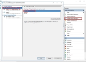
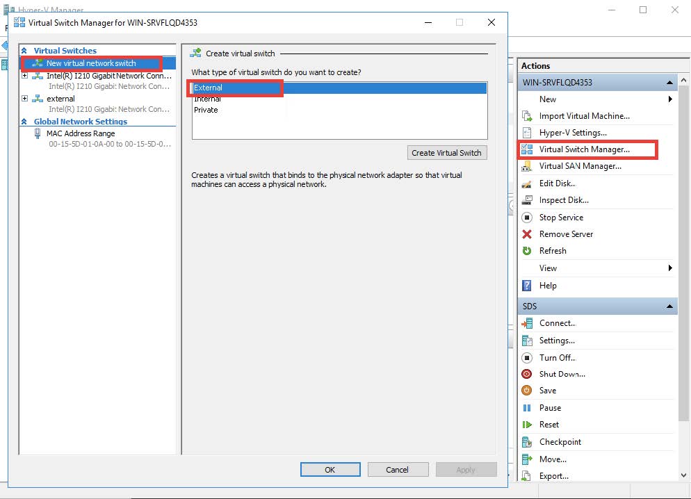
Start the Hyper-V manager and open the Virtual Switch Manager from the right-hand sidebar. Select Create Virtual Switch then choose External Network. The resulting display is shown in the following image.
-
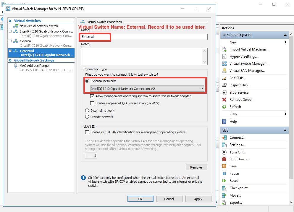
Select the physical network port that is to be used to connect to the outside world. The result appears similar to the sample in the following image.
Enabling Promiscuous Mode
You enable promiscuous mode so that the sensor can monitor all traffic. Promiscuous mode can't be enabled in the user interface, so the following commands must be performed in PowerShell.
In this example, the name of the switch is External. Change this value to the actual name of your switch in the commands.
C:\Users\Administrator> $a = Get-VMSystemSwitchExtensionPortFeature -FeatureId 776e0ba7-94a1-41c8-8f28-951f524251b5
C:\Users\Administrator> $a.SettingData.MonitorMode = 2
C:\Users\Administrator> add-VMSwitchExtensionPortFeature -ExternalPort -SwitchName <name of the switch> -VMSwitchExtensionFeature $a
Obtaining the Virtual Disk Image
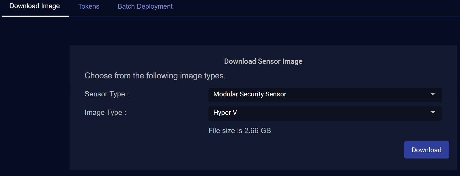
You download the virtual disk image for the Modular Sensor for Hyper-V from the Download Images tab in the System | Deployment | Sensor Installation page. Use the following procedure:
Only users with the Deployment | Sensor Installation | Sensor Image Download privilege assigned to their profile in the System | Role-Based Access Privileges interface can download images.
-
Navigate to the System | Deployment | Sensor Installation page.
-
Set the Sensor Type dropdown to Modular Security Sensor.
-
Set the Image Type toHyper-V.
The display updates to show you the size of the file to be downloaded.

-
Click the Download button. The system downloads the virtual disk image (aella-modular-ds-5.0.0.vhdx) along with its corresponding SHA-1 hash file.
Creating a Modular Sensor VM from the Disk Image
Use the following procedure to create a Modular Sensor virtual machine from the virtual disk image you downloaded from the DP in the previous section.
-
Return to the Hyper-V manager and select Action | New | Virtual Machine....
-
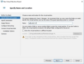
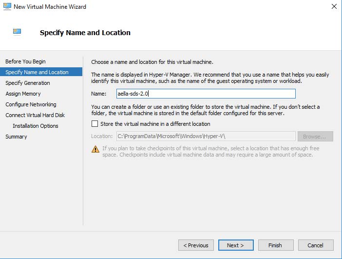
Specify a name for the new Modular Sensor. This can be any legal VM name but it is recommended to adopt a site convention so that the name identifies the type of sensor. The screen appears similarly to the image below.
-
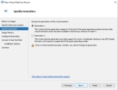
Enter the Generation parameter. The guest Operating System is a 64-bit OS, so Generation 1 is a good choice, as illustrated below:
-
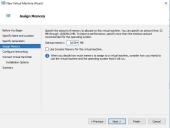
Next, assign memory according to the sensor's expected workload, as stated in Virtual Appliance Sizing Specifications.
-
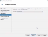
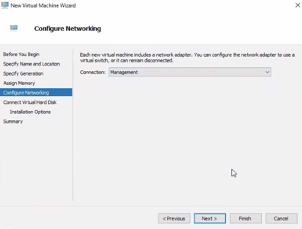
Configure the Management network interface. You can either enter a static IP or use a DHCP server. This is the interface that will be used for the sensor to send its Interflow data records to the data processor. The networking is configured as in the image below:
-
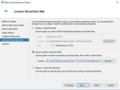
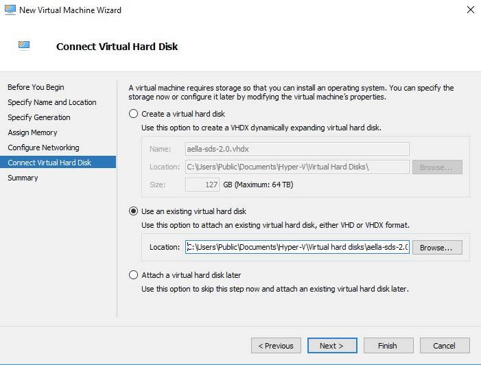
Connect the Virtual Disk image that you downloaded from the DP in Obtaining the Virtual Disk Image. Select the Use existing option, as illustrated below and use the Browse button to point the Location field to the downloaded .vhdx file.
-
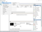
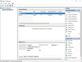
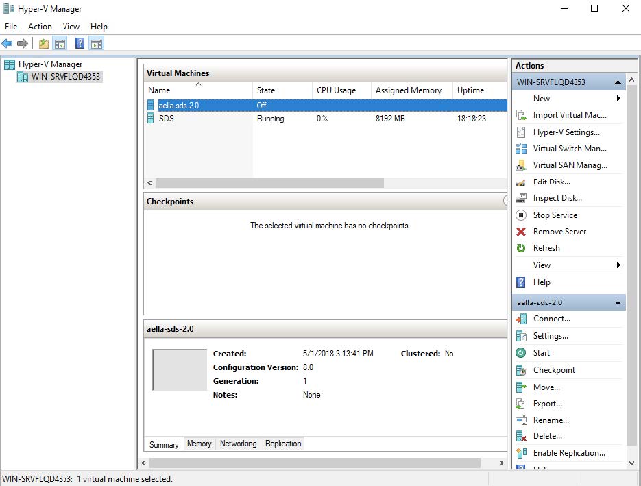
The Modular Sensor VM appears in the Hyper-V Manager similarly to the image below:


Provision Processors
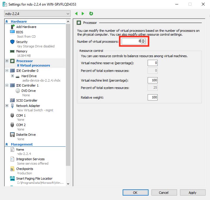
Before you power on the Modular Sensor VM, you must provision sufficient CPU cores to handle the Sensor's expected workload as summarized in in Virtual Appliance Sizing Specifications.
-
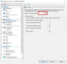
Select the VM in the list and select the Settings | Processor menu options. Then, change the number of processors and click OK.
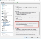
Ensure that Processor Compatibility Mode is Disabled 
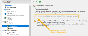
Stellar Cyber sensors deployed in Hyper-V must have the processor compatibility feature disabled to ensure that the SSSE3 instruction set can be used and that aella_flow runs properly. Although the sensor VM starts and appears to run correctly with processor compatibility enabled, stability issues will eventually occur due to high CPU usage.
You can verify that processor compatibility mode is disabled in the same dialog box where you just assigned CPU cores:
-
Expand the Processor entry in the left pane of the Settings dialog box.
-
Click on the Compatibility entry.
-
Ensure that Migrate to a physical computer with a different processor is disabled and click OK.
The image below shows you the option that must be disabled for Stellar Cyber sensors:

Adding an Interface
Before you power on the Modular Sensor VM, you must add a monitoring interface used to gather network data. You connect the monitoring interface to the virtual switch you added in Creating A Virtual Switch. Use the following procedure:
-
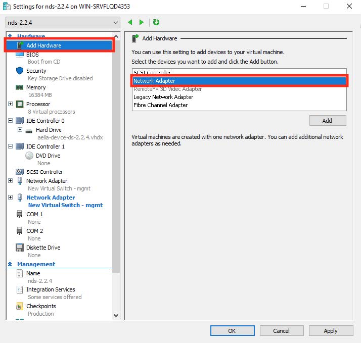
Click Add Hardware | Network Adapter.
You can only add a network adapter to the VM while it is powered off.
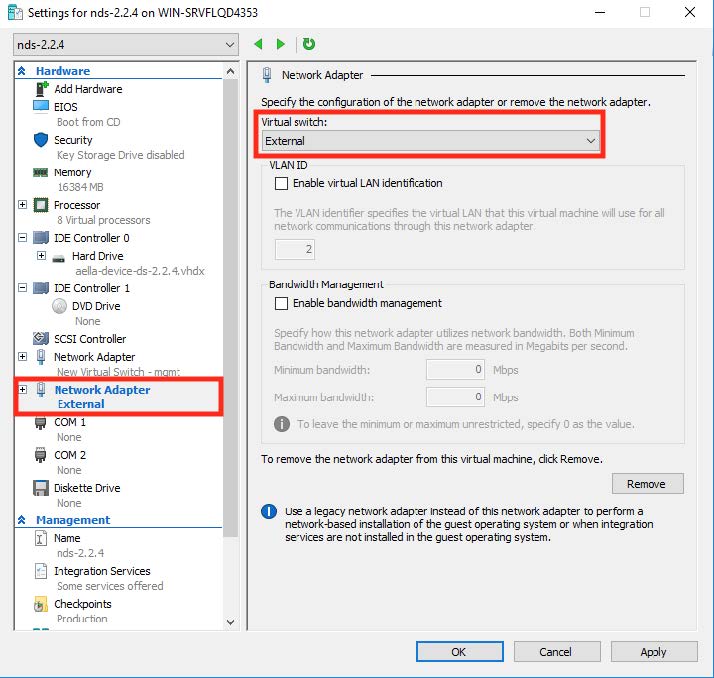
-
Select the virtual switch that you created in in Creating A Virtual Switch, as illustrated below:
-
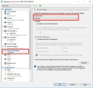
Expand the associated network adapter and click Advanced Features.
-
Set the mirroring mode of the aggregator to Destination, as illustrated below:
-
When you have finished adding the interface, power on the Modular Sensor VM.

Applying a Token to the Installed Sensor
The next step in installing a Modular Sensor is to obtain and apply the token used to authorize and configure the installed sensor.
Obtaining a Token for the Installation
Tokens are required to authorize and configure the installation of a sensor image downloaded from the DP in the System | Deployment | Sensor Installation page. Tokens point the installed sensor to the correct DP, assign the specified tenant, and authorize the sensor installation.
Use the following procedure to obtain a token in the Tokens tab:
-
Navigate to the System | Deployment | Sensor Installation page and click on the Tokens tab.
-
If a token already exists for the target tenant for the sensor installation, you can either use the Copy button to copy it to the clipboard or use the Download button to download it as a file.
-
Copy the token if you plan on applying it by pasting it into a
set token string <token>command in the CLI. -
Download the token as a file if you plan on hosting the file on an HTTP server and referring to it in a
set token url <token url>command.
Refer to Assigning Tokens for a summary of the different ways in which tokens can be applied to a sensor installation.
-
-
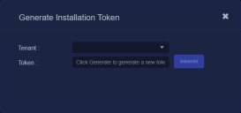
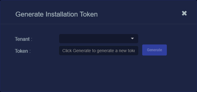
If there is not already an unexpired token for the target tenant, click the Generate button.
The Generate Installation Token dialog appears:
-
Select the tenant for the token from the Tenant dropdown. This is the tenant to which all sensors authorized with this token will be automatically assigned. The dropdown lists all tenants configured for your organization in the System | Tenants page.
-
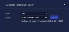
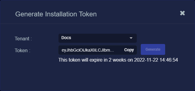
Click the Generate button.
The system generates the token and displays its contents in the Token field. The dialog also updates to display the expiration date for the token, as illustrated below.
-
You can use the Copy button to copy the token to the clipboard immediately, or simply close the dialog and retrieve the token from the Tokens tab later on.
Applying the Token to the Sensor
Tokens are required to complete the installation of a sensor image downloaded from the DP in the Download Image tab.
You apply tokens to sensors as the last step in the overall installation procedure:
- Log in to your new Sensor. The default username/password is aella/changeme. You are immediately prompted to change the password.
-
Apply the token to the installed sensor from the sensor CLI with the
set tokencommand using one of the options in the table below:You only need to use one of the options in the table below. These are just two different ways to do the same thing – apply the token.
Option 1. Copy and Paste the Token String
Copy the token string from the Tokens tab and paste it into the CLI command. The syntax is as follows:
set token string <pasted string>Option 2. Host the Token on an HTTP Server
Download the token as a file from the Tokens tab, upload it to an HTTP server, and reference it in the
set tokencommand. The syntax is as follows:set token url http://<url to token>You can also use an HTTPS server. In that case, the specified URL must also include the username and password for the server using the following syntax:
set token url https://<user:password>@URL> -
The CLI reports that the Sensor token is successfully set.
If you receive an error message instead, it's possible that the token has expired. Refer to the Tokens tab to see the expiration date. If you are using the File technique, it's also possible that an extra space or line may have crept into your text file – check the file to make sure it includes only the token text.
-
Wait a minute or so. Then, verify that the token was successfully applied using any combination of the following techniques:
-
Check the System | Sensors tab in the user interface to see that the sensor has registered itself successfully.
-
Verify that the
show systemcommand shows all services as running. -
Verify that the
show receivercommand displays a receiver. -
Verify that the
show jsoncommand reports some data sent in theBYTE_SENTcolumn.
-
Configuring a Static IP Address (Optional)
By default, the sensor uses DHCP for the management port's IP address. For ease of troubleshooting, however, Stellar Cyber recommends that you reconfigure the management port to use a static IP address. The procedure is as follows:
- Log in to your sensor. The default username/password is aella/changeme, but you changed this when you applied the token in the previous section.
-
You can set IP parameters manually using commands similar to the following (substitute your own IP parameters for the ones shown in bold below):
set interface management ip 192.168.14.100/255.255.255.0
set interface management gateway 192.168.14.1
set interface management dns 8.8.8.8
-
Verify the IP settings with the
show interfacescommand. - Log out with the
quitcommand.
