Installing a Modular Sensor in VMware
This topic describes how to install a Modular Sensor in a VMware environment using the installation file downloaded from the Download Images tab in the System | Deployment | Sensor Installation page. Refer to the following sections for details:
Use our example as a guideline, as you might be using a different software version.
Stellar Cyber does not support the installation of third-party software on its virtual or physical device sensors.
About Modular Sensors
Sensors provide the data gathering foundation for Stellar Cyber's OpenXDR platform, gathering the right data with context. Modular sensors are purpose-built Stellar Cyber sensors that include both the host and the Stellar Cyber monitoring software. They are provided as both physical devices (Photon sensors) and virtual machine images for different target environments.
Previous releases provided a variety of different types of device sensors, including Network, Security, and Modular. Going forward, the only type of device sensor is Modular. You can use the Modular Sensor Profile to enable whatever sensor features you like, creating the same functionality provided by the different sensor types in previous releases.
A modular sensor lets you easily add the features you like to your sensor. This helps simplify your deployment and lets you manage the VM requirements for the sensors based on the modular features they use.
Modular Sensors always include log ingestion. From there, you can enable different features as part of your modular sensor profile:
-
Enable the Network Traffic feature to monitor the virtual environment, the physical environment if connected to the span port of a physical switch, or the LAN segment via a mirror port on a switch. The sensor monitors network and server response times and can identify applications.
The sensor converts that information to metadata and forwards it to the DP as Interflow. The DP can then provide security, DDoS, and breach attempt detections.
-
Enable the Sandbox and IDS features to improve your security posture:
- Sandbox lets you detect malware in files and network traffic through Stellar Cyber's integrated cloud service and also provides anti-virus services.
- IDS lets you detect intrusion attempts using both files and network traffic.
Keep in mind that VM resource requirements increase as you add more features to the Modular Sensor Profile. Refer to Modular Sensor Specifications for details on the resources required to run different combinations of features in a Modular Sensor Profile, as well as how to use the show module and show module request CLI commands to compare provisioned resources against those required to run specific feature combinations. Stellar Cyber only enables a Modular Sensor Profile on a sensor if the host VM's resources can support it.
Site Preparation
Refer to Modular Sensor Specifications for details on the resources required to run different combinations of features in a Modular Sensor Profile. Provision your modular sensor according to the features that you plan on enabling.
You will also need:
- A token obtained from the DP that will manage the sensor.
-
Open firewall ports for log ingestion.
-
Open firewall ports for the features you plan on enabling in the Modular Sensor Profile for this sensor.
One physical port on the system will be configured to receive network traffic to be analyzed. It must have promiscuous mode capability and be connected to an appropriate data source.
In addition, the system BIOS must have VT-d/IOMMU enabled.
Supported ESXi Versions
Sensor installation is supported on the following ESXi versions:
- 8.0
- 7.0
- 6.7
Obtaining the Installation File
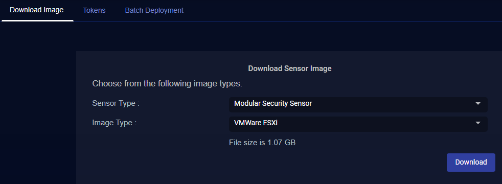
You download the installation file for the Modular Sensor for VMware from the Download Images tab in the System | Deployment | Sensor Installation page. Use the following procedure:
Only users with the Deployment | Sensor Installation | Sensor Image Download privilege assigned to their profile in the System | Role-Based Access Privileges interface can download images.
-
Navigate to the System | Deployment | Sensor Installation page.
-
Set the Sensor Type dropdown to Modular Security Sensor.
-
Set the Image Type to VMware ESXi.
The display updates to show you the size of the files to be downloaded.

-
Click the Download button. The system downloads the installation file (aella-modular-ds-5.0.0.ova) along with its corresponding SHA-1 hash file.
Creating a Virtual Machine Port Group
The following procedure creates a new virtual machine port group with port mirroring capabilities. This is the port group to which we'll connect the new modular sensor's monitor interface for traffic acquisition in the next procedure.
-
Log in to the vSphere Client, right-click the datacenter or host where you want to install the port group, and select the Add Networking option from the context menu that appears.
-
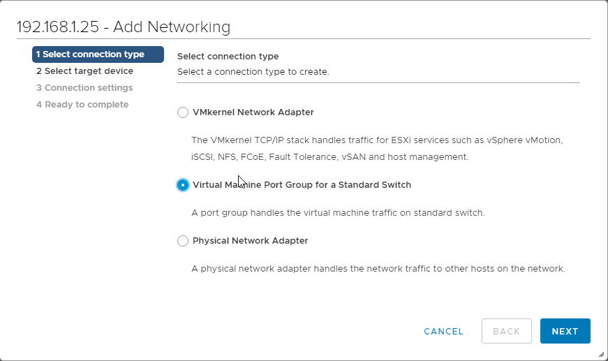
Select the Virtual Machine Port Group for a Standard Switch option and click Next.

-
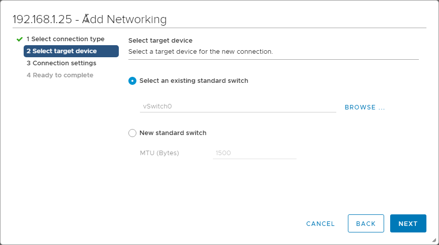
You can add the port group to an existing switch or create a new switch. The following image shows the attachment being made to an existing switch named vSwitch0.

-
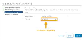
Create a network label with the VLAN ID of 4095, as shown in the image below:
-
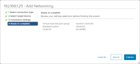
At this point the settings should be complete. Click the Finish button, as illustrated below.
-
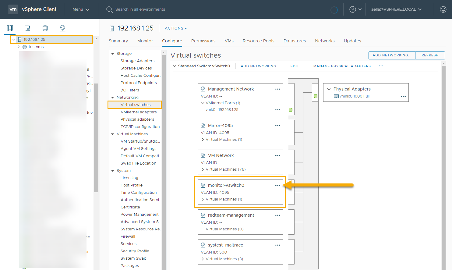
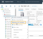
Once setup is complete, you can view the new port group by right-clicking the host where it is installed, selecting Settings from the context menu that appears, and then selecting the Networking | Virtual Switches entry, as shown in the image below.

-
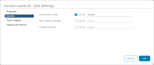
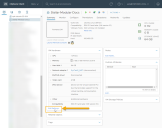
Click the three-dot icon for the port group and select Edit Settings from the context menu that appears.
-
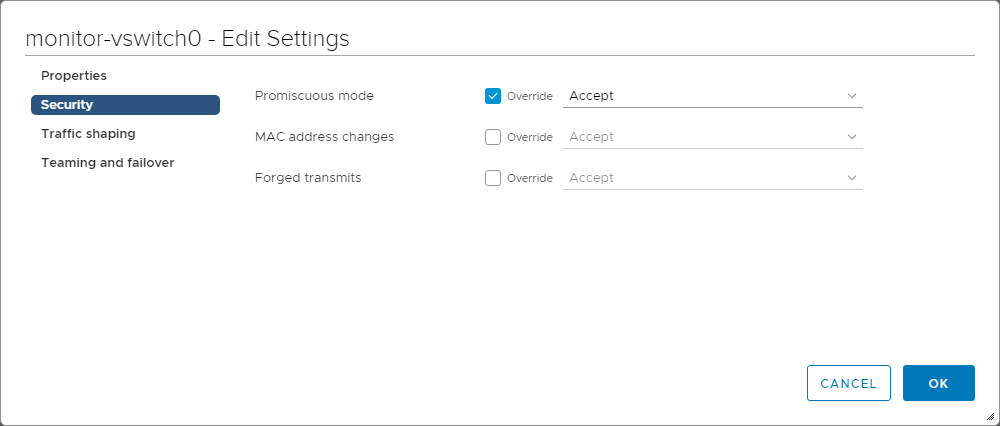
Click on the Security entry in the left navigation panel and enable Promiscuous Mode by checking the corresponding Override and Accept boxes, as shown in the image below. Then, click OK to apply your settings.


Installing the Modular Sensor Image
This section describes how to install the Modular Sensor image you downloaded from the DP at the start of the procedure.
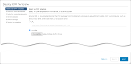
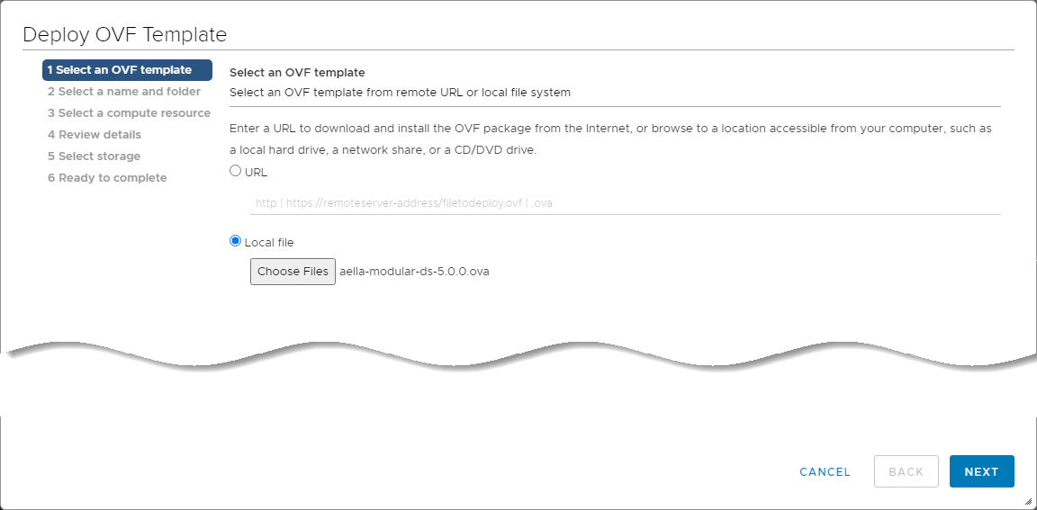
Select the option to deploy a new OVF template wizard and use the Local file option, as shown below.
-
Log in to the vSphere Client.
-
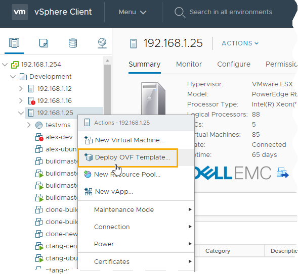
Right-click the datacenter or host where you want to install the Modular Sensor and select the Deploy OVF Template option from the context menu that appears.
The Deploy OVF Template wizard starts.
Stellar Cyber provides the Modular Sensor image as an OVA file. The OVA file includes the necessary OVF file as a component.
-
In the Select an OVF Template step, choose the Local file option and use the Choose Files button to navigate to the OVA file you downloaded in Obtaining the Installation File. Once you have selected the OVA file, click Next.
-
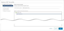
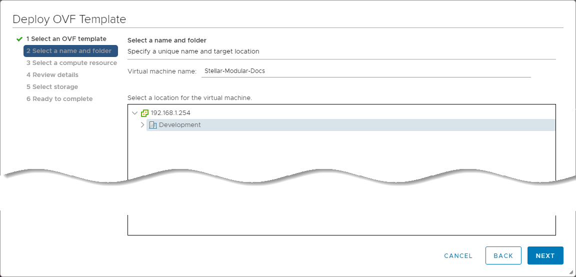
In the Select a name and folder step, provide a name for the virtual machine and select the data center where it will be deployed, as shown below. Then, click Next to continue.
-
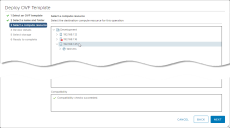
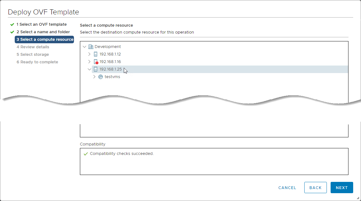
In the Select a compute resource step, select the resource that will run the virtual machine. This should be same resource where the mirror port is hosted. Then, click Next to continue.
-
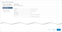
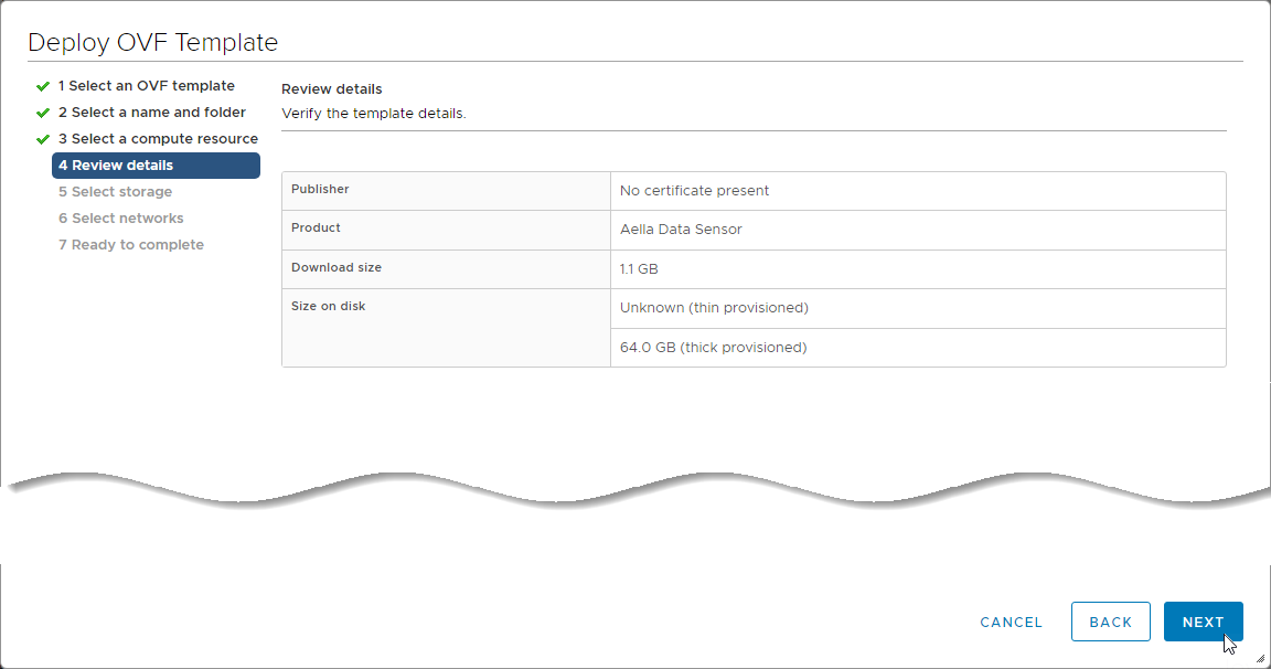
Review the details for the template and click Next to continue.
-
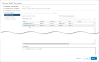
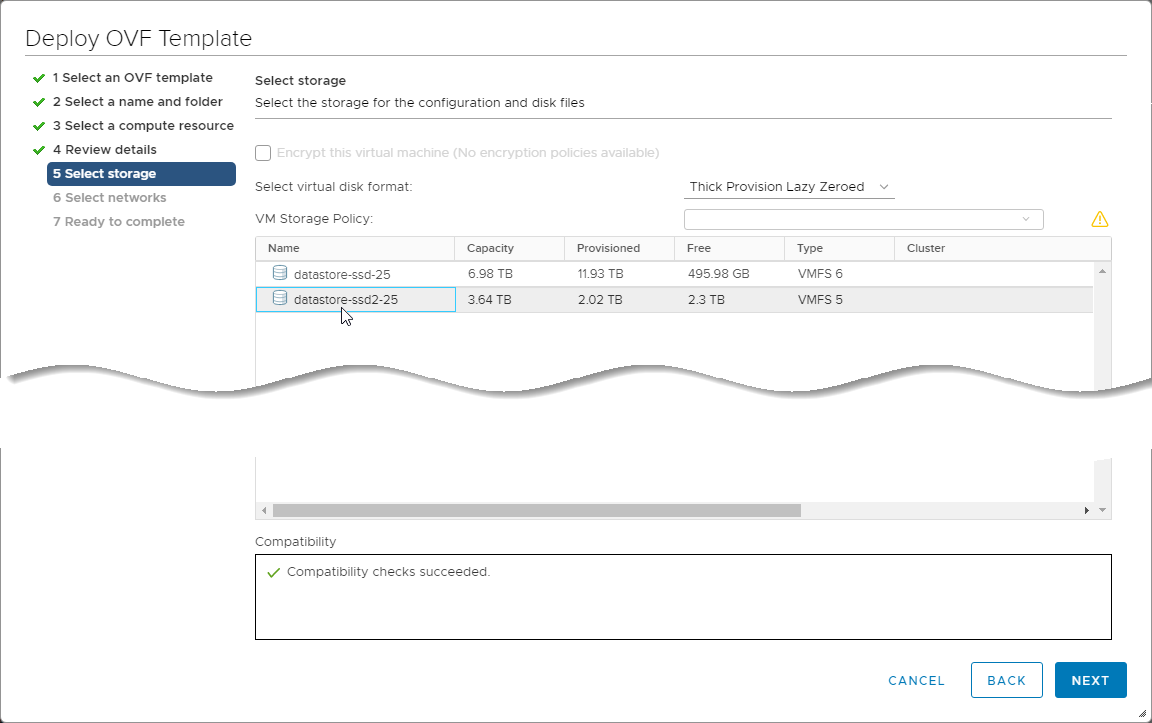
In the Select storage step, select the datastore to be used for the VM's configuration and disk files and click Next to continue.
-
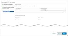
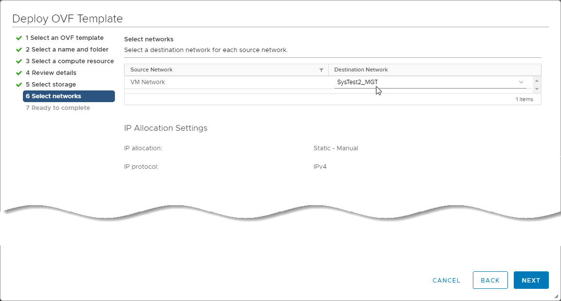
In the Select networks step, use the Destination Network dropdown to select the network where the Modular Sensor's management interface connects. Select a network that can access the DP that will manage the sensor and click NEXT to continue.
-
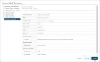
Review the settings in the Ready to complete step and click FINISH to start the deployment.
-
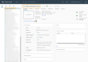
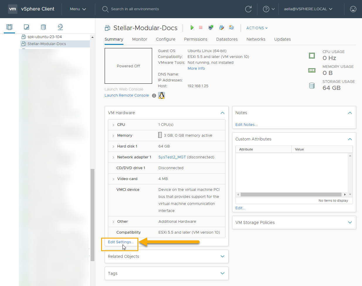
The deployment begins. You can keep tabs on its progress in the Recent Tasks panel at the base of the vSphere Client display. When the deployment completes, you can select its entry in the left navigation panel to see its settings. For example, in the image below, we have selected the Modular Sensor named Stellar Modular Docs.


Adding a Monitoring Interface and Connecting it to the Port Group
The next step is to add a second network adapter to the Modular Sensor virtual machine to be used as a monitor interface. This adapter will monitor traffic on the port group we created in Creating a Virtual Machine Port Group.
You can only add a network adapter to the VM while it is powered off.
-
You should still be in the vSphere Client with the Modular Sensor virtual machine selected. Click the Edit Settings link in the VM Hardware panel.
-
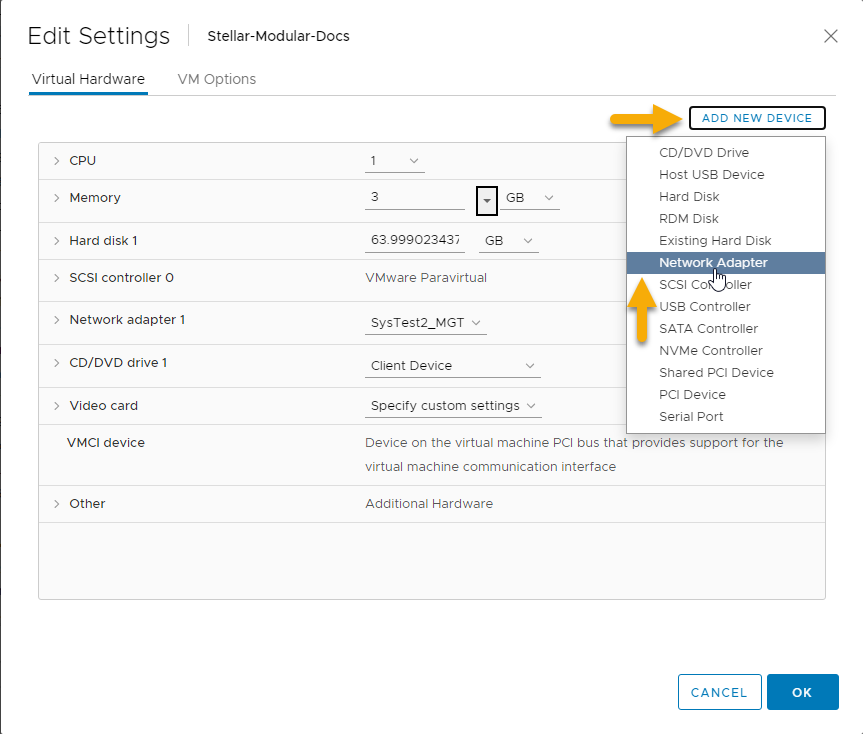
Click the Add New Device button and select Network Adapter from the context menu that appears.
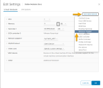
A new entry appears in the Edit Settings dialog box for New Network.
-
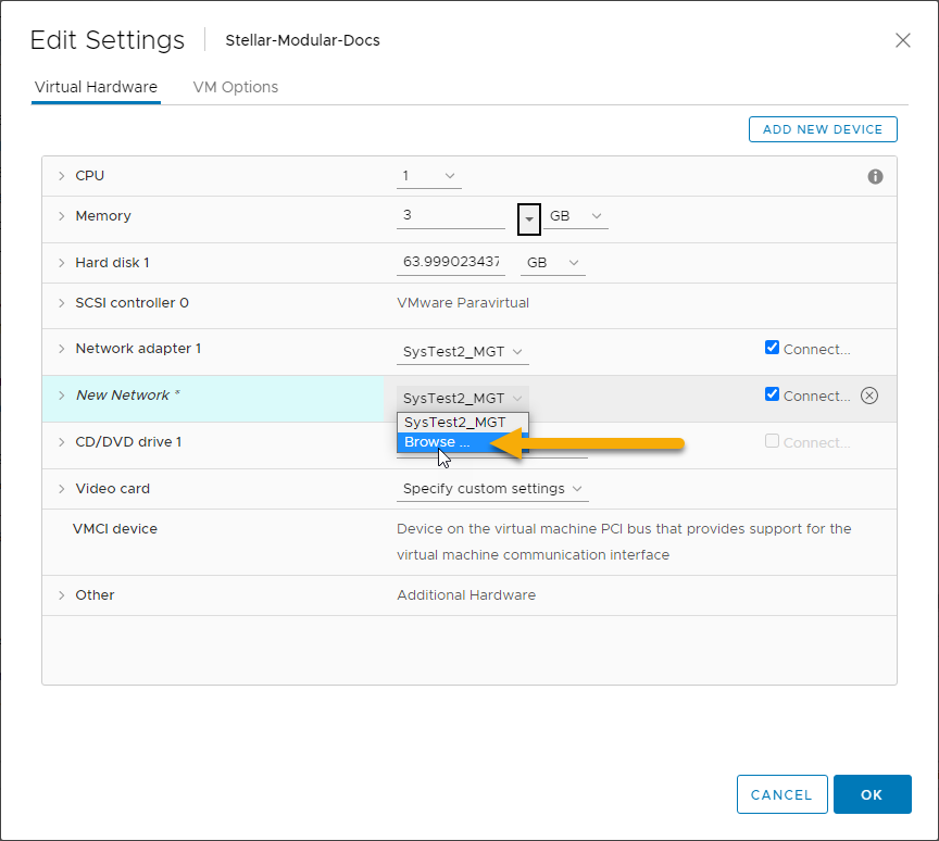
Click the dropdown for the new adapter's network and select the Browse option.

-
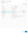
Select the entry for the port group you created in Creating a Virtual Machine Port Group and click OK.
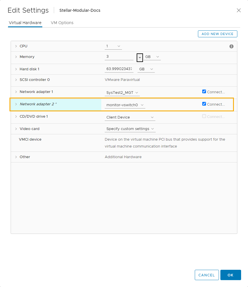
The new network adapter appears in the Edit Settings dialog box connected to the selected port group.
-
Make sure the Connect box for the new network adapter is checked, as illustrated above, and then click OK on the Edit Settings dialog box.
-
At this point the Modular Sensor is installed. If you need to provision any additional resources to support the modular features you anticipate enabling in the sensor's Sensor Profile, now is a good time to do so while it is still powered off. Then, you can start the VM.
Applying a Token to the Installed Sensor
The next step is to obtain and apply the token used to authorize and configure the installed sensor.
Obtaining a Token for the Installation
Tokens are required to authorize and configure the installation of a sensor image downloaded from the DP in the System | Deployment | Sensor Installation page. Tokens point the installed sensor to the correct DP, assign the specified tenant, and authorize the sensor installation.
Use the following procedure to obtain a token in the Tokens tab:
-
Navigate to the System | Deployment | Sensor Installation page and click on the Tokens tab.
-
If a token already exists for the target tenant for the sensor installation, you can either use the Copy button to copy it to the clipboard or use the Download button to download it as a file.
-
Copy the token if you plan on applying it by pasting it into a
set token string <token>command in the CLI. -
Download the token as a file if you plan on hosting the file on an HTTP server and referring to it in a
set token url <token url>command.
Refer to Assigning Tokens for a summary of the different ways in which tokens can be applied to a sensor installation.
-
-
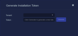
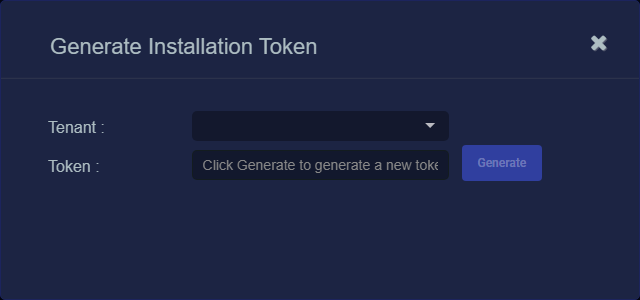
If there is not already an unexpired token for the target tenant, click the Generate button.
The Generate Installation Token dialog appears:
-
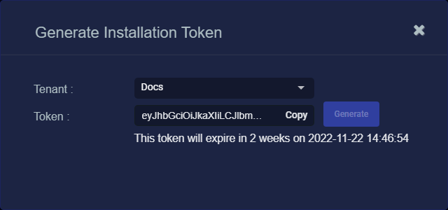
Select the tenant for the token from the Tenant dropdown. This is the tenant to which all sensors authorized with this token will be automatically assigned. The dropdown lists all tenants configured for your organization in the System | Tenants page.
-
Click the Generate button.
The system generates the token and displays its contents in the Token field. The dialog also updates to display the expiration date for the token, as illustrated below.
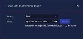
-
You can use the Copy button to copy the token to the clipboard immediately, or simply close the dialog and retrieve the token from the Tokens tab later on.
Applying the Token to the Sensor
Tokens are required to complete the installation of a sensor image downloaded from the DP in the Download Image tab.
You apply tokens to sensors as the last step in the overall installation procedure:
- Log in to your new Sensor. The default username/password is aella/changeme. You are immediately prompted to change the password.
-
Apply the token to the installed sensor from the sensor CLI with the
set tokencommand using one of the options in the table below:You only need to use one of the options in the table below. These are just two different ways to do the same thing – apply the token.
Option 1. Copy and Paste the Token String
Copy the token string from the Tokens tab and paste it into the CLI command. The syntax is as follows:
set token string <pasted string>Option 2. Host the Token on an HTTP Server
Download the token as a file from the Tokens tab, upload it to an HTTP server, and reference it in the
set tokencommand. The syntax is as follows:set token url http://<url to token>You can also use an HTTPS server. In that case, the specified URL must also include the username and password for the server using the following syntax:
set token url https://<user:password>@URL> -
The CLI reports that the Sensor token is successfully set.
If you receive an error message instead, it's possible that the token has expired. Refer to the Tokens tab to see the expiration date. If you are using the File technique, it's also possible that an extra space or line may have crept into your text file – check the file to make sure it includes only the token text.
-
Wait a minute or so. Then, verify that the token was successfully applied using any combination of the following techniques:
-
Check the System | Sensors tab in the user interface to see that the sensor has registered itself successfully.
-
Verify that the
show systemcommand shows all services as running. -
Verify that the
show receivercommand displays a receiver. -
Verify that the
show jsoncommand reports some data sent in theBYTE_SENTcolumn.
-
Configuring a Static IP Address (Optional)
By default, the sensor uses DHCP for the management port's IP address. For ease of troubleshooting, however, Stellar Cyber recommends that you reconfigure the management port to use a static IP address. The procedure is as follows:
- Log in to your sensor. The default username/password is aella/changeme, but you changed this when you applied the token in the previous section.
-
You can set IP parameters manually using commands similar to the following (substitute your own IP parameters for the ones shown in bold below):
set interface management ip 192.168.14.100/255.255.255.0
set interface management gateway 192.168.14.1
set interface management dns 8.8.8.8
-
Verify the IP settings with the
show interfacescommand. - Log out with the
quitcommand.
Configure NTP and Set the Timezone
Stellar Cyber strongly recommends that configure NTP and set the timezone for the sensor.
Refer to Best Practices for NTP and Timezones for details.
