Installing a Modular, Network, or Security Sensor in VMware
A network sensor monitors the virtual environment, the physical environment if connected to the span port of a physical switch, or the LAN segment via a mirror port on a switch. The sensor monitors network and server response times and can identify applications.
The network sensor converts that information to metadata and forwards it to the DP as Interflow. The DP can then provide security, DDoS, and breach attempt detections.
A security sensor operates as a network sensor and adds:
- sandbox
- anti-virus
- IDS
You can also tunnel traffic over VXLAN from an agent sensor, network sensor, or container sensor to the security sensor so it can inspect those environments.
A modular sensor lets you easily add the features you like to your sensor. This helps simplify your deployment and lets you manage the VM requirements for the sensors based on the modular features they use.
You can install a modular, network, or security sensor on VMware.
Site Preparation
Click to see the minimum system requirements for installing a modular, network, or security sensor.
You will also need to:
- Open firewall ports for a network sensor
- Open firewall ports for a security sensor
- Open firewall ports for log ingestion
One physical port on the system will be configured to receive network traffic to be analyzed. It must have promiscuous mode capability and be connected to an appropriate data source.
In addition, the system BIOS must have VT-d/IOMMU enabled.
Downloading Images
The virtual machine images for modular, network, and security sensors in VMware can be downloaded from the Stellar Cyber production server at the links in the table below.
Installation links point to the most recent release. To download a different version, simply substitute the version you want for the version specified in the link.
| Description | Version | URL |
|---|---|---|
| Modular Sensor | 4.3.7 | https://acps.stellarcyber.ai/release/4.3.7/datasensor/aella-modular-ds-4.3.7.ova |
| Network Sensor | 4.3.7 | https://acps.stellarcyber.ai/release/4.3.7/datasensor/aella-device-ds-4.3.7.ova |
| Security Sensor | 4.3.7 | https://acps.stellarcyber.ai/release/4.3.7/datasensor/aella-device-sds-4.3.7.ova |
Contact Stellar Cyber support (support@stellarcyber.ai) for login credentials.
Alternatively a curl command in a shell user environment can be used to download the images. To download a security sensor version 4.3.7 the following command can be used:
curl -k -u login:password https://acps.stellarcyber.ai/release/4.3.7/datasensor/aella-device-sds-4.3.7.ova -o aella-device-sds-4.3.7.ovaSupported ESXi Versions
Sensor installation is supported on the following ESXi versions:
- 8.0
- 7.0
- 6.7
Installation Steps
Once the prerequisites have been met, use the following procedure to install the sensor:
Use our example as a guideline, as you might be using a different software version.
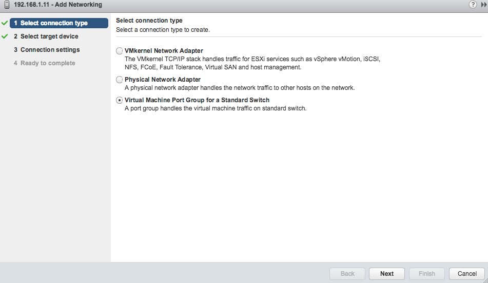
Create a new virtual switch with port mirroring capabilities. Start with the add-networking wizard function and select the Virtual Machine Port Group option as shown in the following image.
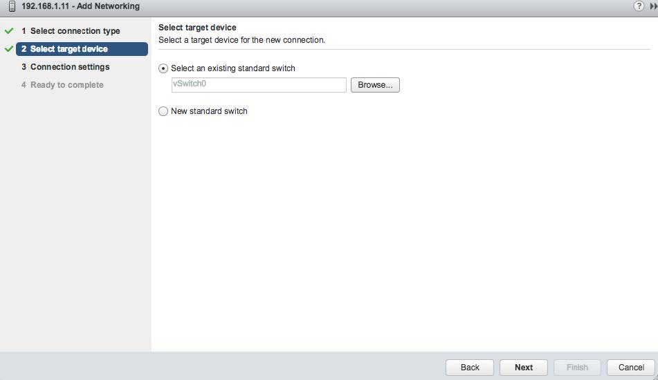
You can add the port to an existing switch or create a new switch. The following image shows the attachment being made to an existing switch named vSwitch0.
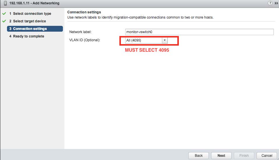
Create a network label with the VLAN ID of 4095. This is shown in the following image.
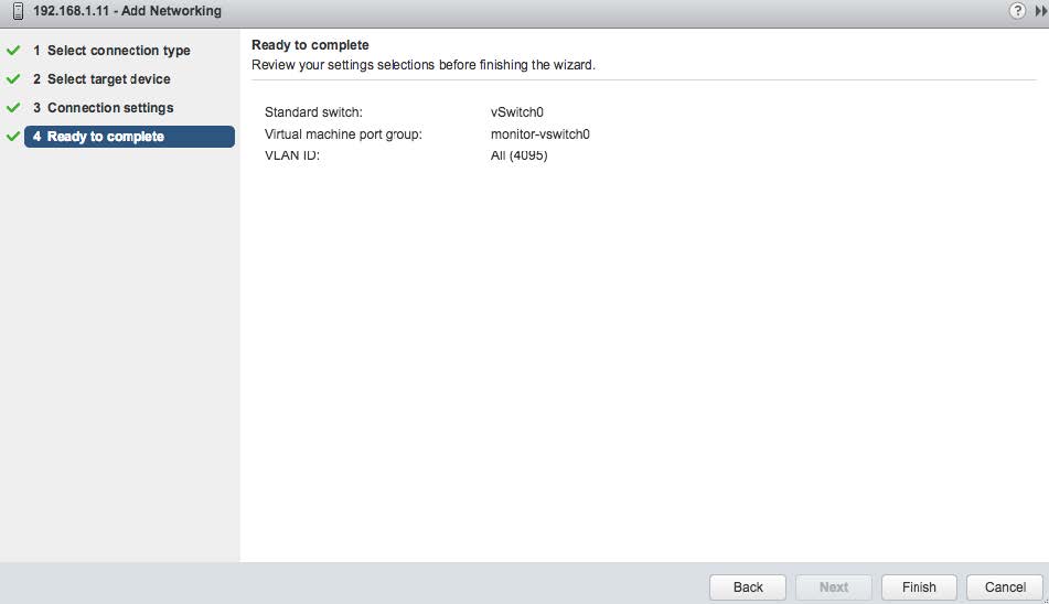
At this point the settings should be complete. Select the "FINISH" button as shown below.
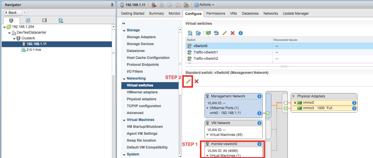
When completed, the resulting switch can be seen in the Networking section of the vCenter Navigator as shown in the following image. Select the network connection as shown in "STEP 1" and then the Edit button shown as "STEP 2".
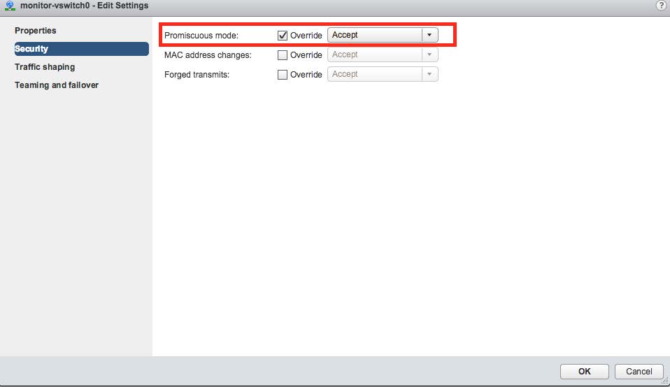
Select the "Security" panel option and enable Promiscuous Mode by selecting the appropriate Override and Accept controls as shown in the following image.
You can repeat the above steps as necessary to monitor additional ports.
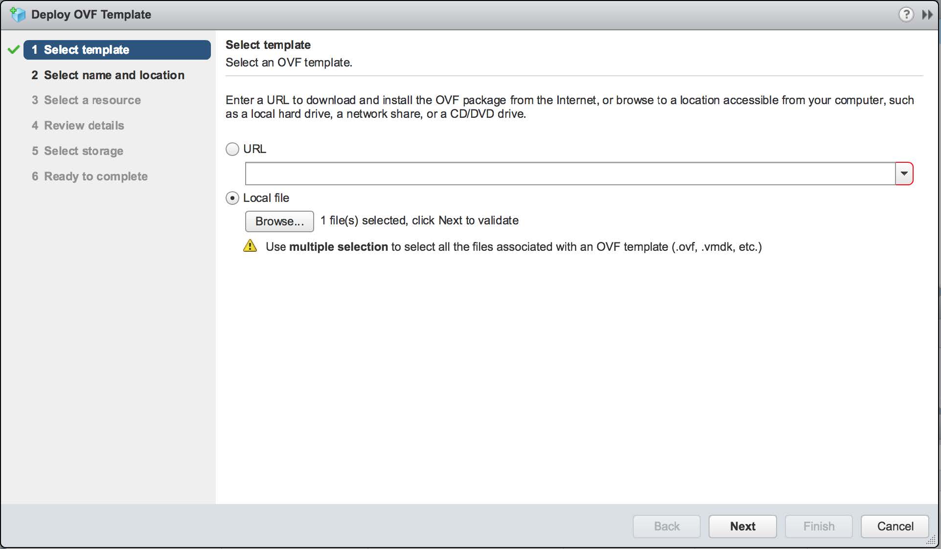
The next steps create the VM. Select the option to deploy a new OVF template wizard and use the Local file option, as shown below.
The Stellar Cyber distribution provides an OVA file, which is a format that includes the requested OVF file as a component.
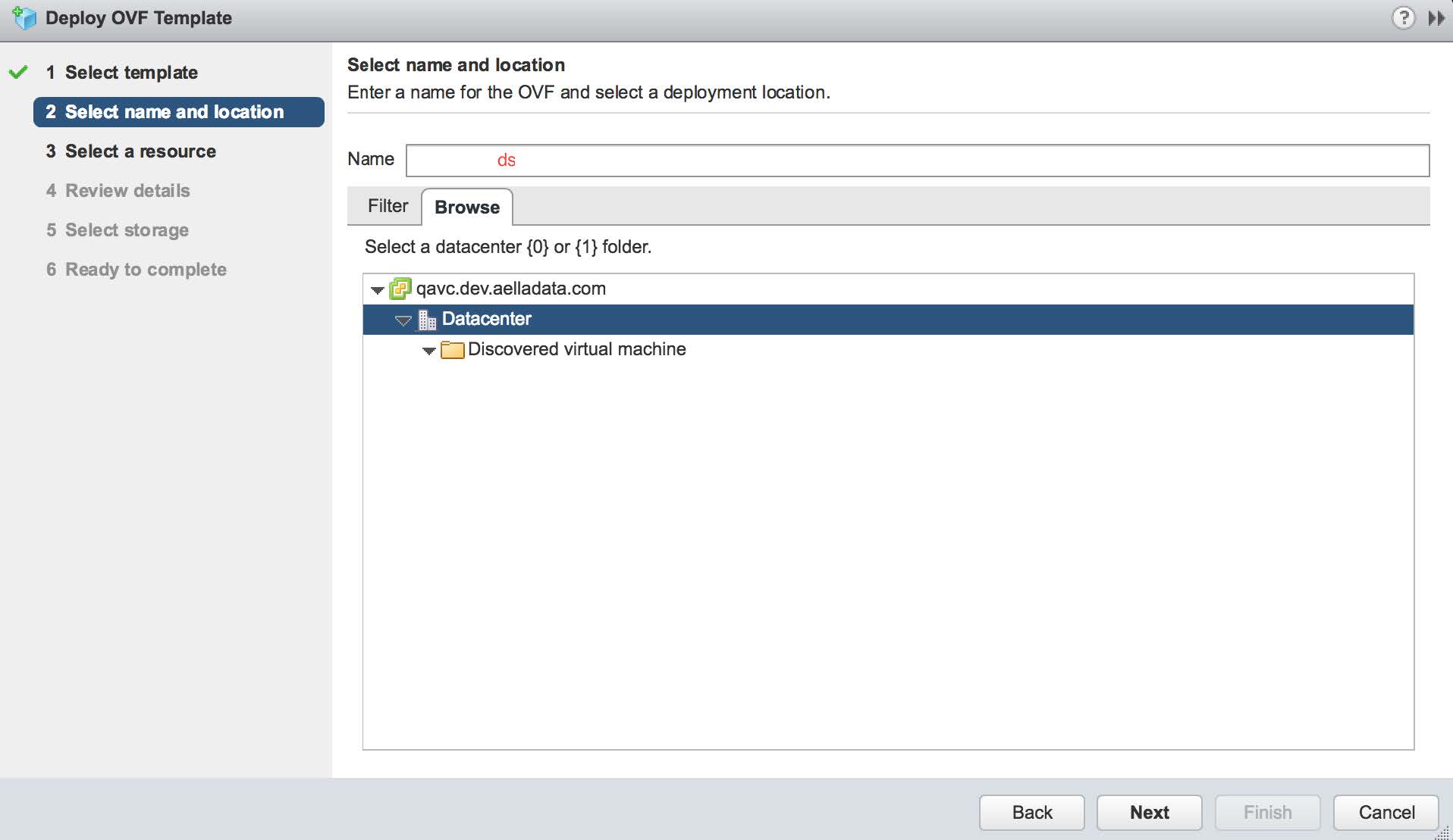
On the next screen provide the VM a name and select the appropriate data center where it will be deployed, as shown below:
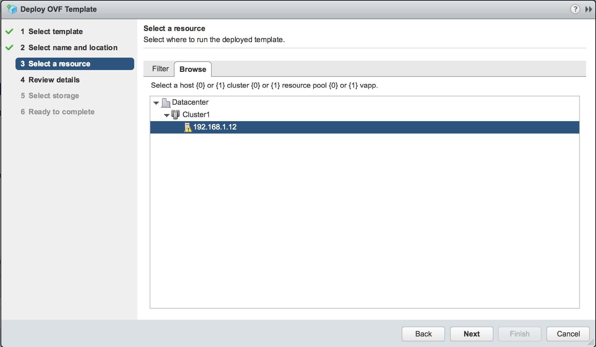
Within the data center, there may be more than one resource that can run the VM. Select the one which hosts the mirror port. A simple configuration is shown in the following image:
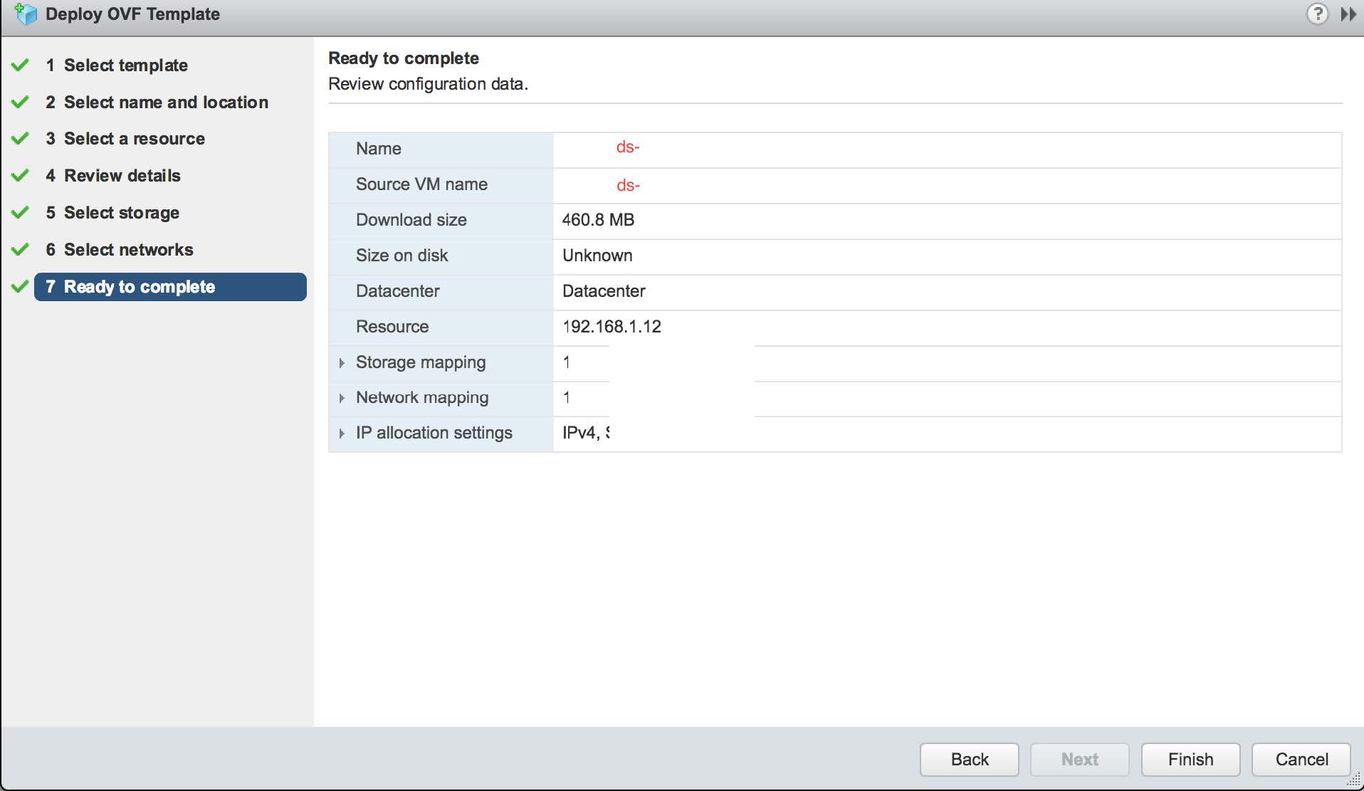
Once the selections are made, the summary page appears as follows. If the settings are correct, click the Finish button shown in the following image:
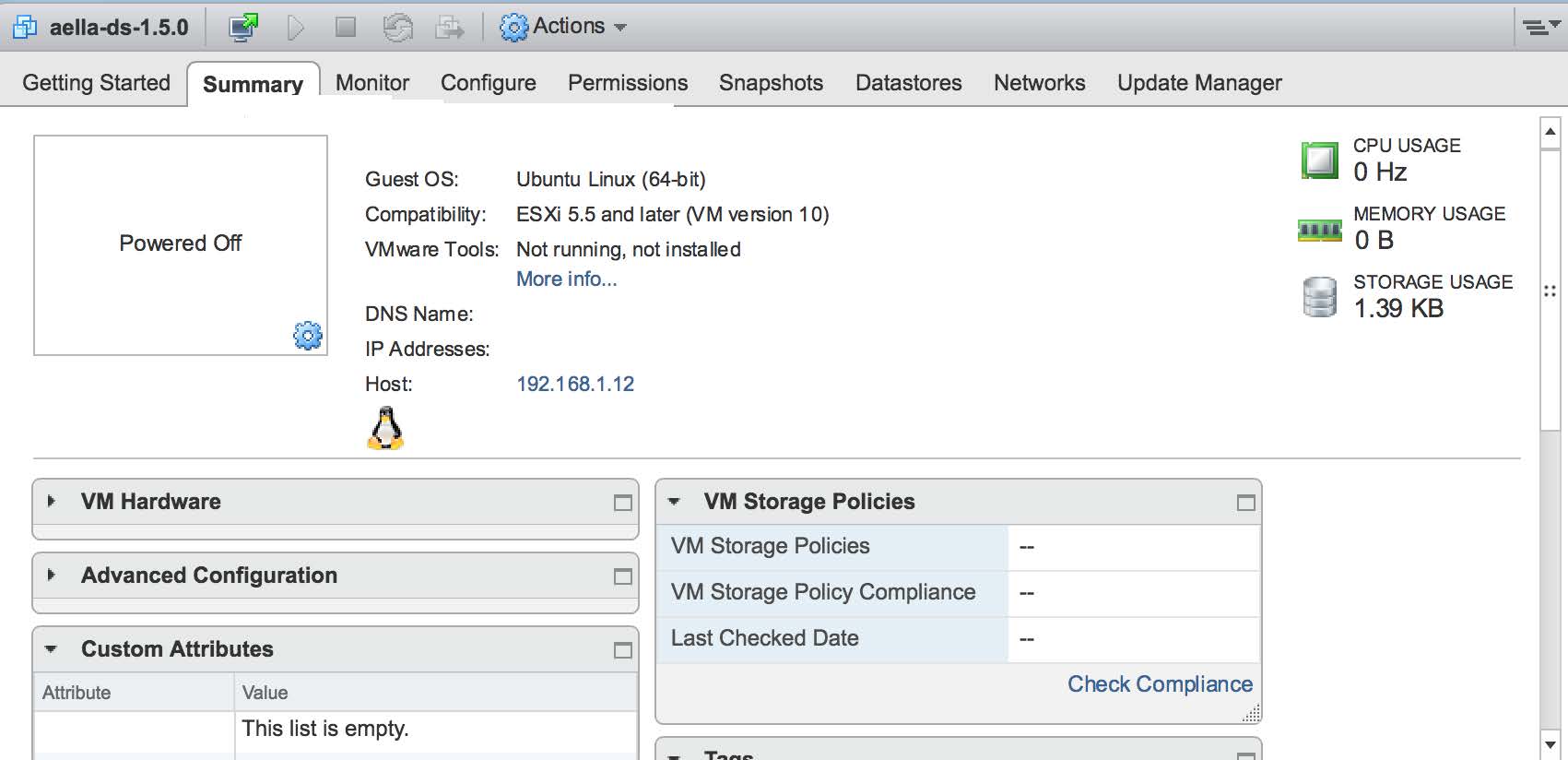
The VM is loaded into the hypervisor management and can then be seen in the vCenter summary page. An example of this is shown in the following image:
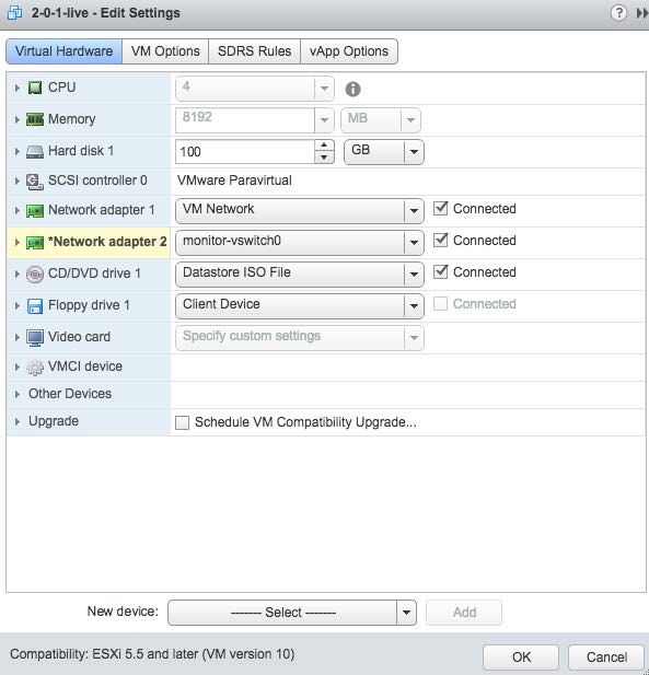
Expand the Virtual Hardware sub-page. The Management channel used by the sensor is implemented over "Network Adapter 1" which needs to be connected. Select it as shown in the following image:
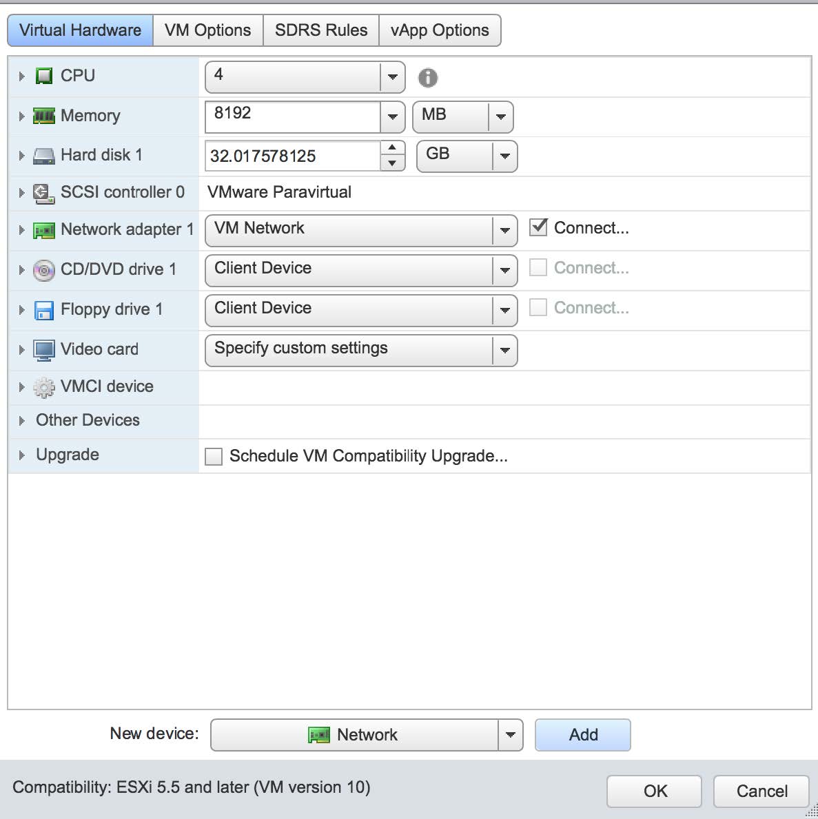
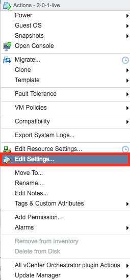
Select the "Edit Settings" menu item to add a second adapter. This is the network interface that will be used to monitor traffic on the virtual switch we created in prior steps. This is shown in the next two images. Note that you can only add a network adapter to the VM while it is powered off:
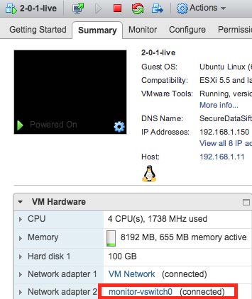
At this point the Sensor is installed and can be started. An example of this is shown in the following image:
Connecting the Sensor to the DP
To connect to the DP:
- Log in to your new
-
Change the password.
After you change the password, your session closes automatically. When you log back in with your new credentials, the prompt changes to DataSensor>.
-
Set IP parameters for the management port. You can use either a static IP address or a DHCP server, if available.
Stellar Cyber recommends using a static IP address for ease of troubleshooting.
The commands are as follows:
Configuration Type
Commands
Static IP Substitute your own IP parameters for those shown in bold.
set interface management ip 192.168.14.100/255.255.255.0set interface management gateway 192.168.14.1set interface management dns 8.8.8.8DHCP set interface management ip dhcp -
Verify the IP settings with the
show interfacescommand. -
Set the host name. The host name is displayed in Stellar Cyber and should be unique for each sensor:
set hostname <new hostname> -
If necessary, set the proxy HTTP server:
set proxy http://<proxy IP address:port> -
If this
set tenant_id <Tenant ID>command to specify the name of that tenant. For example:set tenant_id MyTenant -
Use the
set cmcommand to specify the IP address to reach the management interface of the Data Processor. For a DP cluster, this is the IP address of the DL-master's management interface. For a single DP deployment, this is simply the DP's management IP address. You can specify either an IP address or a hostname. For example:set cm 192.168.44.10or:
set cm example.company.com If you specify a hostname rather than an IP address, the system attempts to verify the hostname with the DNS server. If the DNS server is not reachable, the system reports the error and lets you either proceed with the configured hostname or quit. This way, you can specify a hostname for the
 set cmdestination in an offline environment without access to a DNS server. - Verify your settings with the
show cmcommand. You should see the IP address of the DP listed as the CM Controller and the Status should be Established. - Log out with the
quitcommand.
The
Authorize the Sensor
You must authorize the sensor when it appears in the network.
You can authorize multiple sensors at a time. So if you're installing multiple sensors, install them all, then authorize them all at once.
