Installing a Data Processor in VMware (Cluster)
You can deploy the Stellar Cyber data processor (DP) on a dedicated VMware ESXi server with support for up to 300GB of daily ingestion.
In this model, you install Stellar Cyber with separate VMs for the DA and DL and optional cluster support for additional DA and DL worker nodes. You also have the option of installing as an integrated DP, with a Security Data Sensor VM installed on the same ESXi server as the DP VMs.
Stellar Cyber deployment consists of the following major steps:
- Before You Begin
- Minimum System Requirements
- Install and Configure VMware ESXi
- Configure Storage
- Deployment Models
- Create vSwitches and Port Groups
- Create Virtual Machines
- Configuring Roles on Data Processor VMs
- Connecting the SDS to the Data Lake Master (Integrated Data Processor Deployments Only)
- Adding a Second Hard Disk to Data Lake VM
- Configuring CPU Scheduling Affinity
Before You Begin
Make sure the target system meets the minimum system requirements for installing a DP. The installation requires:
- Dedicated ESXi server running VMware ESXi 8.0, 7.0 or 6.7. You can install ESXi yourself or have it pre-installed by the server vendor (for example, Dell).
-
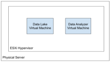
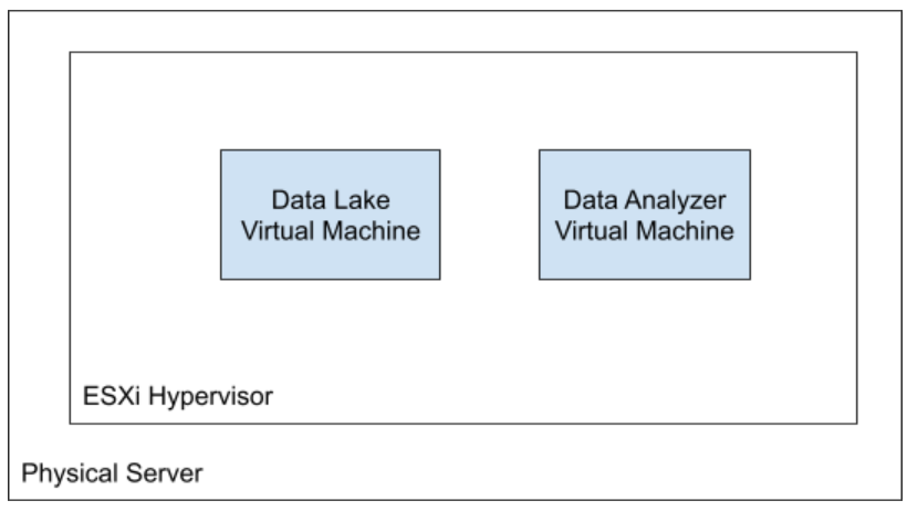
The server must operate as a dedicated server for ESXi and a single Stellar Cyber deployment's virtual machines, as summarized in the figure below:
- Management IP addresses for ESXi host and all VMs
- 1 public IP address for each non- clustered DP (for management access)
- 2 public IP addresses for each DP in a cluster (1 for management access, and 1 for the cluster)
- 1 public IP address for each Security Sensor (SS), if the SS is deployed in a different virtual private cloud (VPC) than the DP
- NFS, SCP, and S3 for data and configuration back-up
The internal network of the DP uses the 172.17.0.0/16 and 10.244.x.0/24 subnets. If you use these subnets elsewhere in your network, change them to avoid conflicts. If you cannot change them, contact Stellar Cyber technical support.
To prepare:
- Open ports on your firewall. These are required for the DP to communicate with sensors.
- Follow the link they send you.
-
Download the OVA file for the DP installation from the following URL and remember where you saved it. You will use this file to install both the DL and the DA. If you already have credentials:
https://acps.stellarcyber.ai/release/4.3.7/dataprocessor/aella-dataprocessor-4.3.7.ova
-
Download the OVA file for the SDS installation from the following URL and remember where you saved it:
https://acps.stellarcyber.ai/release/4.3.7/datasensor/aella-device-sds-4.3.7.ova
Installation links point to the most recent release. To download a different version, simply substitute the version you want for the version specified in the link.
-
Keep your OTP handy for configuring the DP.
After license activation, you can find the OTP for your installation in the Licensing page.
Contact Stellar Cyber support (support@stellarcyber.ai) for login credentials and a one-time password (also known as a License Key).
Minimum System Requirements
The target ESXi server must have sufficient resources to support separate virtual machines for the Data Analyzer, Data Lake, and, if installing as an Integrated Data Processor, the Security Data Sensor. The specifications in the table below are sufficient to support a Stellar Cyber deployment with up to 300GB of daily ingestion.
You can also install the DP as an all-in-one (AIO) with lower minimum specifications and support for only 50 GB of daily ingestion. Refer to Installing an All-In-One Data Processor in VMware.
Keep in mind the following:
-
Each VM (DA, DL, and SDS) must be thick-provisioned and requires 500 GB of SSD disk space.
-
You can install all three of the VMs in the same datastore if there is sufficient space for both the VMs and the 12+ TB required for the Data Lake's ElasticSearch data. However, Stellar Cyber recommends that the Data Lake uses a dedicated datastore.
| Deployment Type | Resource | Host | DL | DA | SDS |
|---|---|---|---|---|---|
| Recommended (Production)
(DL and DA VMs) |
CPU/vCPU | 44 physical (88 cores/hyperthreads) | 40 | 44 | - |
| RAM (GB) | 256 | 136 | 64 | - | |
| OS SSD Disk Space | 1 TB | 500 GB | 500 GB | - | |
| Data Lake Disk Space (TB) | 16 TB | 12+ TB | - | - | |
| Integrated Data Processor (DL, DA, and SDS VMs) |
CPU/vCPU | 44 physical (88 cores/hyperthreads) | 28 | 28 | 28 |
| RAM | 256 | 136 | 64 | 32 | |
| OS SSD Disk Space | 1 TB | 500 GB | 500 GB | 500 GB | |
| Data Lake Disk Space | 16 TB | 12+ TB | - | - | |
| Minimum Configuration for Separate DP VMs
You can still deploy separate DL and DA VMs so long as the ESXi host is provisioned with sufficient CPUs to support the following minimum configuration: |
CPU/vCPU | 16 | 16 | - | |
| RAM | 128 | 64 | - | ||
| OS SSD Disk Space | 500 GB | 500 GB | - | ||
| Data Lake Disk Space | 2+ TB | - | - | ||
Scaling Up Performance with a DP Cluster
You can configure up to ten DP servers to operate in a cluster to achieve improved Stellar Cyber performance. Stellar Cyber’s cluster testing indicates the following performance guidelines when adding additional DPs to a cluster:
-
With data replication disabled, the aggregated ingestion throughput grows linearly with the number of DP servers.
-
With data replication enabled (the default), the aggregated ingestion throughput is about 30% lower than the throughput without data replication.
Install VMware ESXi
Refer to the VMware documentation for detailed instructions on installing VMware ESXi.
Configure Storage
Stellar Cyber recommends that you use one datastore with sufficient capacity for the VM system disks and a second datastore for the disk used to store the Data Lake's Elasticsearch data. This procedure explains how to:
-
Increase the capacity of the existing datastore so that it has sufficient space for the VM system disks (at least 2 x 500 GB=1 TB for a Production deployment and 3 x 500 GB=1.5 TB for an Integrated DP deployment), as explained in the system requirements).
-
Create and resize a new datastore so that it has sufficient capacity for the Data Lake's Elasticsearch data (12+ TB).
Both of these procedures require you to select the physical devices to be used for a datastore. If you do not see the disks you expect when you come to the Select device step, refer to Disks Not Appearing in vSphere Client for instructions on identifying and partitioning the physical disks so that they appear correctly.
You can also install all components in a single datastore if it has sufficient space. However, Stellar Cyber recommends a dedicated datastore for the Data Lake's Elasticsearch data.
Increasing the Capacity of a Datastore
Use the following procedure to increase the capacity of the existing datastore:
-
Open a VMware Host Client connection to the ESXi server.
-
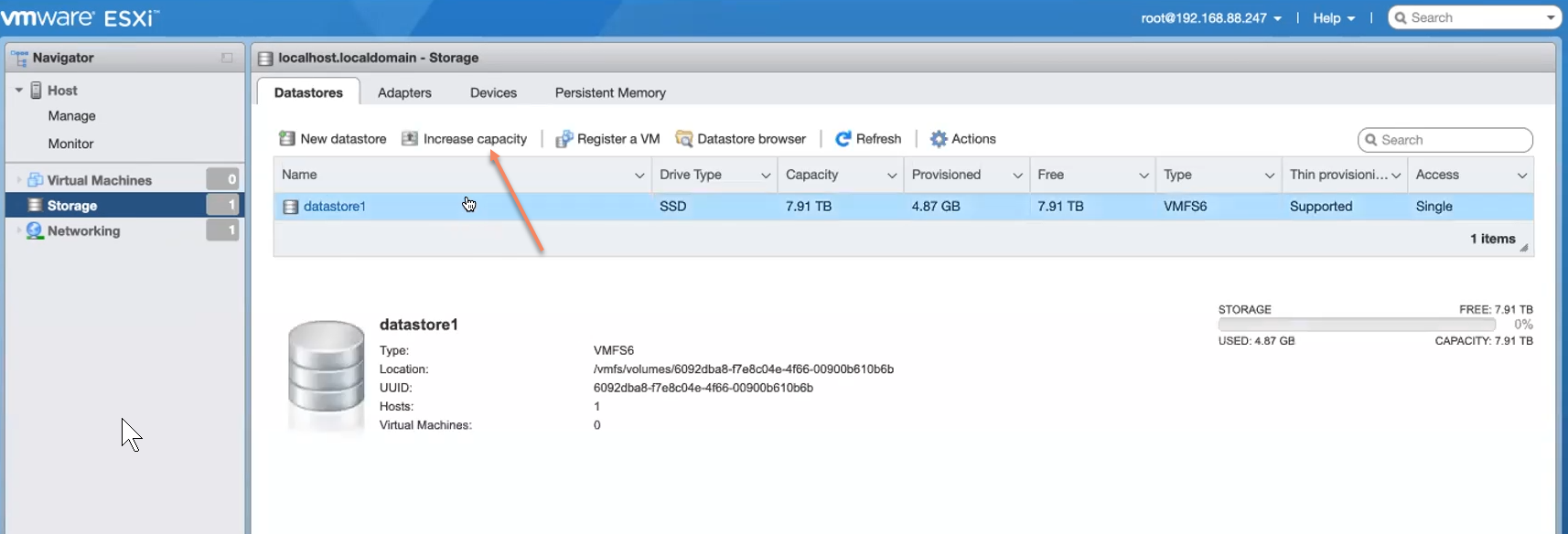
Navigate to the Storage > Datastores tab.
-
Select the entry for the existing datastore and click the Increase capacity button, as shown in the example below.
-
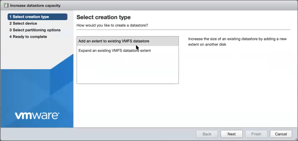
In Select creation type, select Add an extent to existing VMFS datastore and click Next.

-
In Select device, choose the disk partitions with available space to be used to increase the datastore's capacity and click Next.
If you do not see the disks you expect, refer to Disks Not Appearing in vSphere Client.
-
In Select partitioning options, choose Use full disk and VMFS 6 and click Next.
-
In Ready to complete, review the configuration details and click Finish.
-
If a warning appears informing you that the disk contents will be replaces, click Yes to proceed.
Creating a New Datastore
Use the following procedure to create a new datastore and increase its size so that is has capacity for the Data Lake's Elasticsearch data:
-
Open a VMware Host Client connection to the ESXi server.
-
Navigate to the Storage > Datastores tab.
-
Click New datastore.
-
In Select creation type, select Create new VMFS datastore and click Next.
-
In Select device, select where to create the new VMFS partition.
-
Enter a name for the new datastore.
-
Select a device to add the datastore to.
The list contains only devices that have enough available space. Make sure you choose a device with sufficient space for the Data Lake's Elasticsearch data (12+ TB).
If you do not see the disks you expect, refer to Disks Not Appearing in vSphere Client.
-
-
In Select partitioning options, choose Use full disk and VMFS 6 and click Next.
-
In Ready to complete, review the configuration details and click Finish.
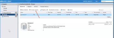
Verifying a Datastore's Disks
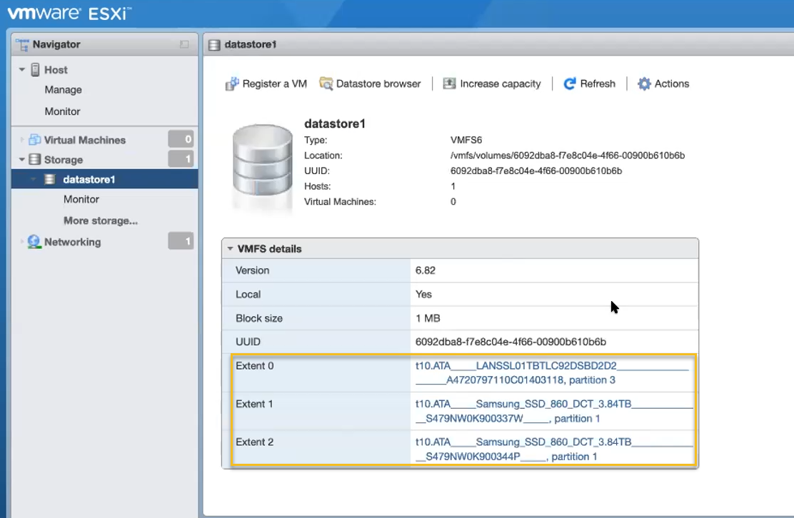
You can verify which physical disks a datastore is using by navigating to the Storage > Datastores tab and clicking the entry for the datastore in the Name column. A screen appears showing the datastore's configuration, including the constituent disks, as highlighted in the example below:
Disks Not Appearing in vSphere Client?
If disks do not appear for selection when you are creating or enlarging a datastore, use the following procedure to format them from the ESXi command line using the partedUtil utility.
Refer to the VMware documentation for details on using the partedUtil utility.
-
Open a console session with the ESXi server.
-
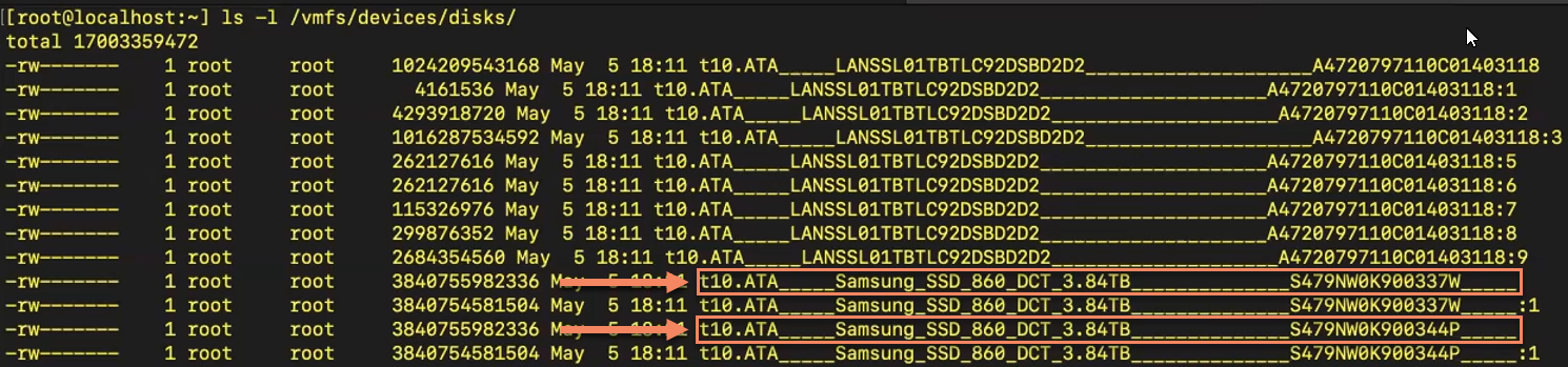
Use the following command to list the disk devices that can be managed by partedUtil:
ls -l /vmfs/devices/disks
The figure below shows the two disks that need to be formatted.

-
Use the partedUtil mklabel <path to disk> gpt command to format the disks with a GPT format.The figure below shows the necessary commands for the current example:


Deployment Models
There are two basic deployment models for Stellar Cyber in VMware – basic deployments and cluster deployments. The two models use different approaches for the network connections of the following Stellar Cyber VMs:
-
DLm – Data Lake Master VM
-
DAm – Data Analyzer Master VM
-
SDS – Security Data Sensor VM
Note that the SDS VM is only installed on the same ESXi server as the DL and DA in Integrated DP deployments; it is typically installed elsewhere in Production deployments.
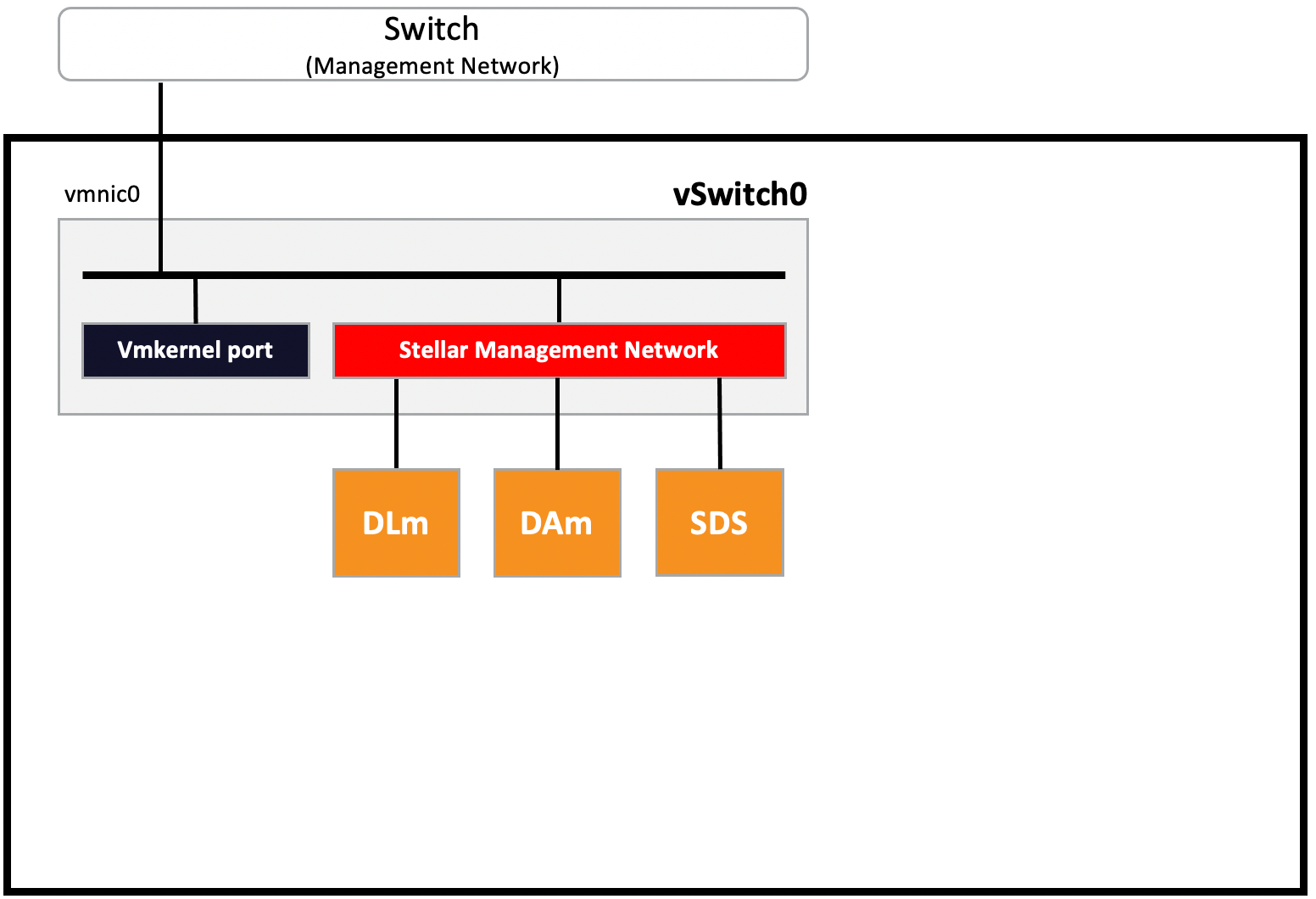
Basic Deployment: All VMs on Same Port Group
In a basic deployment, all of the Stellar Cyber VMs are connected to the same VMware port group (Stellar Management Network in the figure below). In this model, you do not need to create a new vSwitch or port groups – the default ones are sufficient. The figure below shows the default VM Network port group renamed as Stellar Management Network.
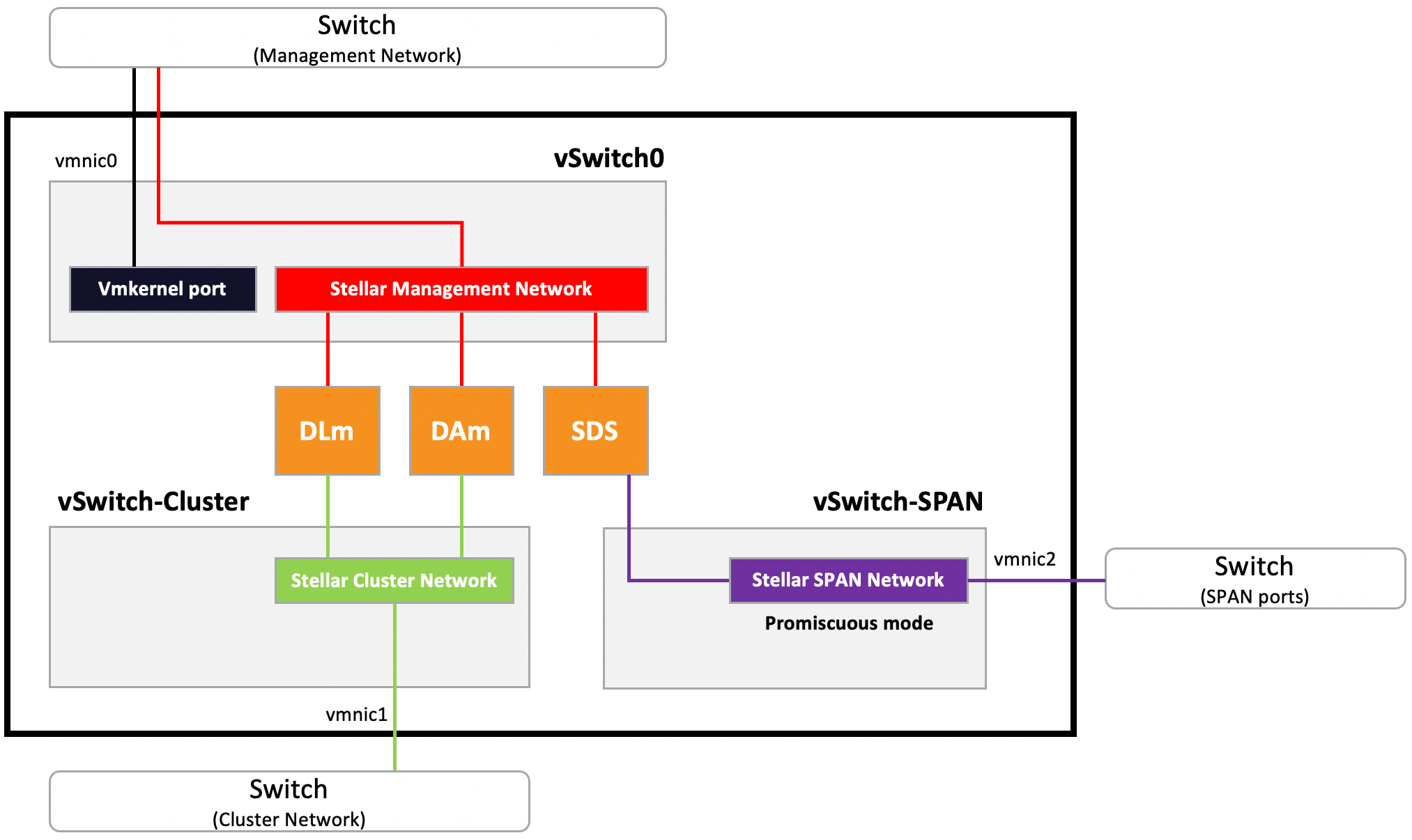
Cluster Deployment: Separated Cluster, Management, and SPAN Traffic
In a cluster deployment, you create separate vSwitches and port groups that separate Stellar Cyber's cluster and management traffic from monitored (SPAN network) traffic. In this model, you create the following additional vSwitches and port groups in Create Virtual Switches and Port Groups:
-
vSwitch-Cluster with Stellar Cluster Network port group.
-
vSwitch-SPAN with Stellar SPAN Network port group (Integrated DP deployments only).
In addition, you'll add the following additional network adapters in Add Network Adapters:
-
DLm and DAm VMs– A second network adapter connected to Stellar Cluster Network.
-
SDS VM (Integrated DP Deployments Only) – A second network adapter connected to Stellar SPAN Network.
Create Virtual Switches and Port Groups
This section describes how to create the virtual switches and port groups for a cluster deployment. You only need to create these items if you are using a cluster deployment.
Basic deployments can use the default virtual switch and port (vSwitch0 and VM Network), although you may want to rename the default port group to Stellar Management Network to match the example in Basic Deployments.
Create Virtual Switches
This procedure creates the following virtual switches:
-
vSwitch-Cluster – for traffic between the DLm and DAm and clustered worker nodes.
-
vSwitch-SPAN – for the SDS to receive mirrored traffic from SPAN ports. You only need to create this vSwitch for Integrated DP deployments.
To create the virtual switches:
Use our example as a guideline, as you might be using a different software version.
-
Open a client connection to the ESXi server. We are using the VMware Host Client in this example.
-
Navigate to the Networking > Virtual switches tab.
-
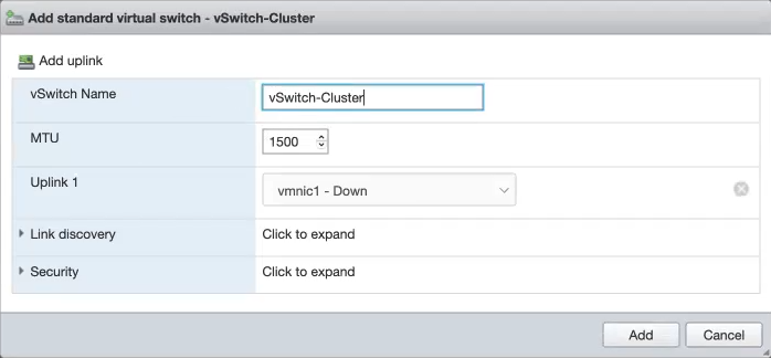
Click the Add standard virtual switch button and make the following settings:
-
vSwitch Name – vSwitch-Cluster for the first switch; vSwitch-SPAN for the second.
-
MTU – Leave set to 1500.
-
Uplink 1 – Select vmnic1 for the first switch and vmnic2 for the second.
-
Link discovery – Leave set to default.
-
Security – Leave set to default.
The figure below illustrates the settings for vSwitch-Cluster:
-
-
Click Add to add the switch to the list.
-
Repeat this procedure to add vSwitch-SPAN. Make sure you use the corresponding vSwitch Name and Uplink.
Create Port Groups
This procedure creates the following port groups:
-
Stellar Cluster Network port group on vSwitch-Cluster.
-
Stellar SPAN Network port group on vSwitch-SPAN. You only need to create this port group for Integrated DP deployments.
To create the virtual switches:
Use our example as a guideline, as you might be using a different software version.
-
Open a client connection to the ESXi server. We are using the VMware Host Client in this example.
-
Navigate to the Networking > Port groups tab.
-
Click the Add port group button.
-
We'll add Stellar Cluster Network on vSwitch-Cluster first. Set the options in the Add port group dialog box as follows:
-
Name – Stellar Cluster Network.
-
VLAN ID– Leave set to 0.
-
Virtual switch –Select vSwitch-Cluster from the dropdown list.
-
Security – Leave set to defaults.
-
-
Click Add to add the switch to the list.
-
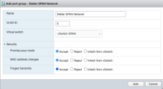
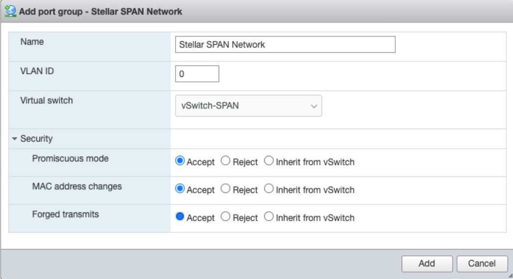
Next, we'll add Stellar SPAN Network on vSwitch-SPAN. Remember, we only need to do this for Integrated DP deployments. Repeat Steps 2-3, above, and then set the options in the Add port group dialog box as follows:
-
Name – Stellar SPAN Network.
-
VLAN ID– Leave set to 0.
-
Virtual switch –Select vSwitch-SPAN from the dropdown.
-
Security – This port group is for the SDS, which must be able to monitor traffic. So, the security settings are a little different, as follows:
-
Promiscuous mode – Accept
-
MAC address changes – Accept
-
Forged transmits – Accept
The figure below shows the Add port group dialog box as it appears for the Stellar SPAN Network port group:
-
-
-
Click Add to add the switch to the list.
Rename Default Port Group
The ESXi server is installed with a default port group named VM Network on vSwitch0 on vmnic0. We'll rename this port group as Stellar Management Network to make it clear that we're using it for management traffic and to match the diagram in Cluster Deployments. Use the following procedure.
-
Open a client connection to the ESXi server. We are using the VMware Host Client in this example.
-
Navigate to the Networking > Port groups tab.
-
Select the entry for the default VM Network port group and click the Edit settings button.
-
In the dialog box that appears, change the port group's name to Stellar Management Network and click Save.
Create Virtual Machines
This procedure uses the OVA files you downloaded in Before You Begin to create the following virtual machines:
- Data Lake Master – Named dl-master in this example. Created with aella-dataprocessor-4.3.7.ova.
- Data Analyzer Master – Named da-master in this example. Created with aella-dataprocessor-4.3.7.ova.
- Security Data Sensor (Integrated DP Deployments Only) – Named datasensor in this example. Created with aella-device-sds-4.3.7.ova.
Noticed that you deploy the same OVA file twice to create the DL and DA. Later on, you'll assign roles to the two VMs that differentiate their functions. Some of the values you provide in the procedure below are different depending on which VM you are creating – the procedure indicates the correct values for each VM.
To create the VMs:
Use our example as a guideline, as you might be using a different software version.
-
Open a client connection to the ESXi server. We are using the VMware Host Client in this example.
-
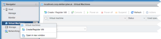
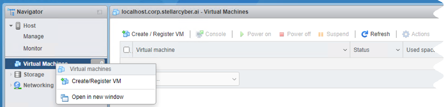
Right-click Virtual Machines in the Navigator panel and select Create/Register VM from the context menu that appears.
-
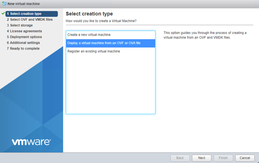
In the Select creation type page, choose the Deploy a virtual machine from an OVF or OVA file option and click Next.

- In the Select OVF and VMDK files page:
Supply a name for the VM. In this example, we use the following names:
dl-master (Data Lake)
da-master (Data Analyzer)
datasensor (Security Data Sensor; Integrated DP deployments only)
Select the OVA file you stored in Before You Begin that corresponds to the installation type:
DL or DA – aella-dataprocessor-4.3.7.ova
Security Data Sensor – aella-device-sds-4.3.7.ova
- Click Next.
-
In the Select storage page, select the datastore for the VM and click Next.
-
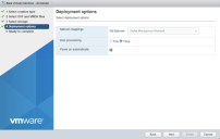
Set the following options in the Deployment options page:
-
Network mappings – Set to the Stellar Management Network you created by renaming the default port group.
-
Disk provisioning – Set to Thick.
-
Power on automatically – Leave unchecked
Make sure that Power on automatically is not selected. If the VM powers on automatically, you cannot change the settings while it powers up, which can take a while.
-
-
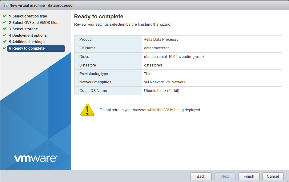
Click Next. The Ready to complete screen appears.
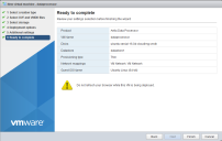
- Review your configuration.
- Click Finish. The VM is created and appears in the list of recent tasks at the bottom of the screen.
- Repeat this procedure for the additional VMs required for your deployment type (Data Analyzer Master and, if an Integrated DP deployment, Security Data Sensor).

Provisioning CPUs and Memory
Before you power on the VMs, use the Edit Settings dialog box to provision sufficient CPU and memory for each VM's role. The following procedure explains how to provision resources.
Note that you will perform this procedure for each VM in your deployment using the minimum system requirements for its intended role and deployment type, as summarized in Minimum System Requirements.
-
Open a client connection to the ESXi server. We are using the VMware Host Client in this example.
-
Click the Virtual Machines entry in the Navigator panel.
-
Right-click on your new VM in the Virtual Machines window and select Edit settings from the context menu that appears. The Edit settings screen appears.
-
Use the CPUs option to provision sufficient vCPUs for the VM's role and deployment type, as summarized in Minimum System Requirements.
-
Use the Memory option to provision sufficient RAM for the VM's role and deployment type, as summarized in Minimum System Requirements.
-
If you are using the Cluster deployment model, now is a good time to add the second network adapter since you are already in the Edit settings dialog box. Refer to Adding Network Adapters.
-
Click Save to apply your changes.
Adding Network Adapters (Cluster Deployments)
If you are using the Cluster deployment model, you must add a second network adapter to each of the VMs in your deployment:
- DLm and DAm – A second network adapter connected to Stellar Cluster Network.
-
SDS (Integrated DP Deployments Only) – A second network adapter connected to Stellar SPAN Network.
Use the following procedure to add a second network adapter:
-
Open a client connection to the ESXi server. We are using the VMware Host Client in this example.
-
Click the Virtual Machines entry in the Navigator panel.
-
Right-click on your new VM in the Virtual Machines window and select Edit settings from the context menu that appears. The Edit settings screen appears.
-
Click the Virtual Hardware tab and click Add network adapter.
-
Set the following options for the new adapter:
-
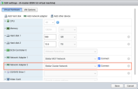
Data Lake Master and Data Analyzer Master – Use the dropdown to connect the new adapter to the Stellar Cluster Network you created in Create Port Groups.
-
Security Data Sensor – Use the dropdown to connect the new adapter to Stellar SPAN Network you created in Create Port Groups.
-
For all VM types, make sure the Connect checkbox is checked.
The figure below shows the settings for the dl-master:
-
- Click Save to apply your changes.
- Repeat this procedure for the additional VMs required for your deployment type (Data Analyzer Master and, if an Integrated DP deployment, Security Data Sensor).
- When you have finished configuring all necessary VMs, power them on by selecting their entries in the Virtual Machines list and clicking the Power on button.

Configuring Roles on Data Processor VMs
When the VMs for your deployment are up and running, you are ready to log in to their consoles and assign roles.
You do this differently depending on whether you are configuring a Basic deployment or a Cluster deployment. The main difference is that in a cluster deployment, you must enable and configure the second vNIC in the DLm and DAm VMs as a cluster interface. The sections below have the details.
Configuring Roles in a Basic Deployment
To configure the Data Lake Master role:
- Open a console connection to the DLm VM.
- Log in. The default user/password is aella/changeme. You are immediately prompted to change the password.
- Change the password.
-
By default, the VM uses DHCP to obtain an IP address. You can use the show interface command to see the IP address. If you prefer to assign static IP information, use the following commands:
set interface management ip [IP address for your DP, including netmask]
set interface management gateway [IP address of your gateway]
set interface management dns [IP address of your DNS, or 8.8.8.8]
-
Assign a unique hostname to the VM with the set hostname command. For example:
set hostname dl-master
If you change the hostname again after installation completes, you must run the
rebootandresetcommands from the VM command line. -
Reboot the VM with the reboot command.
-
Open a new console connection to the DLm VM if it is not still open and log in.
-
Assign the DL-master role to the VM with the following command:
set role DL-master
-
Configure the cluster name and size with the following commands:
set cluster_name dl-master
set cluster_size 1
-
Use the set cm command to specify the IP address of the Data Lake's cluster interface. Because this is a Basic deployment without a dedicated Cluster network, this is just the IP address of the DLm's management interface. You can use the show interface command to see this address, as in the example below:
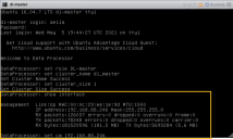
The syntax for the command is illustrated in the figure above and is as follows:
set cm [IP address of the DLm's management interface] -
Supply the License Key you received from Stellar Cyber in your Welcome Letter with the following command:
set otp [License Key you received from Stellar Cyber]The License Key is also referred to as a one-time password, or OTP.
After license activation, you can find the OTP for your installation in the Licensing page.
-
Reset the VM with the following command:
reset
-
Confirm the reset. The image is downloaded (which can take a while, depending on your network) and installed.
-
Verify that everything is installed, ready, and running with the
show statuscommand. A screen similar to the following appears as it is installing:

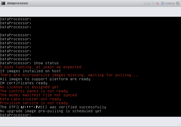
When it finishes the status is similar to:
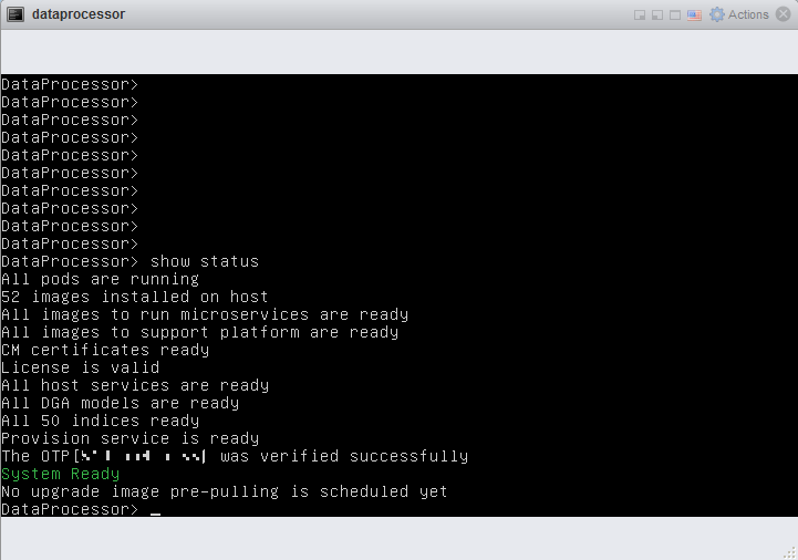
The installation of the Data Lake Master is complete. Next, configure the Data Analyzer.
To configure the Data Analyzer Master role:
You configure the Data Analyzer Master role by first assigning its role as a resource in its CLI. Then, once the VM is up and running, you convert it to a Data Analyzer Master from within Stellar Cyber. Use the following procedure:
- Open a console connection to the DAm VM.
- Log in. The default user/password is aella/changeme. You are immediately prompted to change the password.
- Change the password.
-
By default, the VM uses DHCP to obtain an IP address. You can use the show interface command to see the IP address. If you prefer to assign static IP information, use the following commands:
set interface management ip [IP address for your DP, including netmask]
set interface management gateway [IP address of your gateway]
set interface management dns [IP address of your DNS, or 8.8.8.8]
-
Assign a unique hostname to the VM with the set hostname command. For example:
set hostname da-master
-
Reboot the VM with the reboot command.
-
Open a new console connection to the DAm VM if it is not still open and log in.
-
Assign the resource role to the VM with the following command:
set role resource
-
Use the set cm command to specify the IP address of the Data Lake's management interface. Because this is a Basic deployment without a dedicated Cluster network, this is just the IP address of the DLm's management interface. You configured this in the previous procedure. For example:
set cm 192.168.88.246
-
Reset the VM with the following command:
reset
-
Verify that everything is installed, ready, and running with the
show rolecommand. When the system reportsresource, the installation of the DAm VM is complete. Next, we need to convert it from its current resource role to a DA-Master from within the Stellar Cyber user interface. Use the following procedure.
If you change the hostname again after installation completes, you must run the reboot and reset commands from the VM command line.
To convert the DAm VM's role from "resource" to "DA-Master"
-
Once the show status command for the DLm reports System Ready and the show role command for the DAm reports Resource, log in to the DLm's graphical user interface with a web browser. For example:
https://<DLm Management IP Address>
The default credentials are a username of admin with a password of changeme.
-
Navigate to the System | Data Processor | Resources page and make sure you see a resource that is ready and available.
Do not edit the resource directly in the System | Data Processor | Resources page. Instead, use the System | Data Processor | Data Analyzer page to convert the resource's role, as described below.
-
Navigate to the System | Data Processor | Data Analyzer page and click the Create button to create a new DA cluster. Refer to Managing the Data Analyzer for details.
-
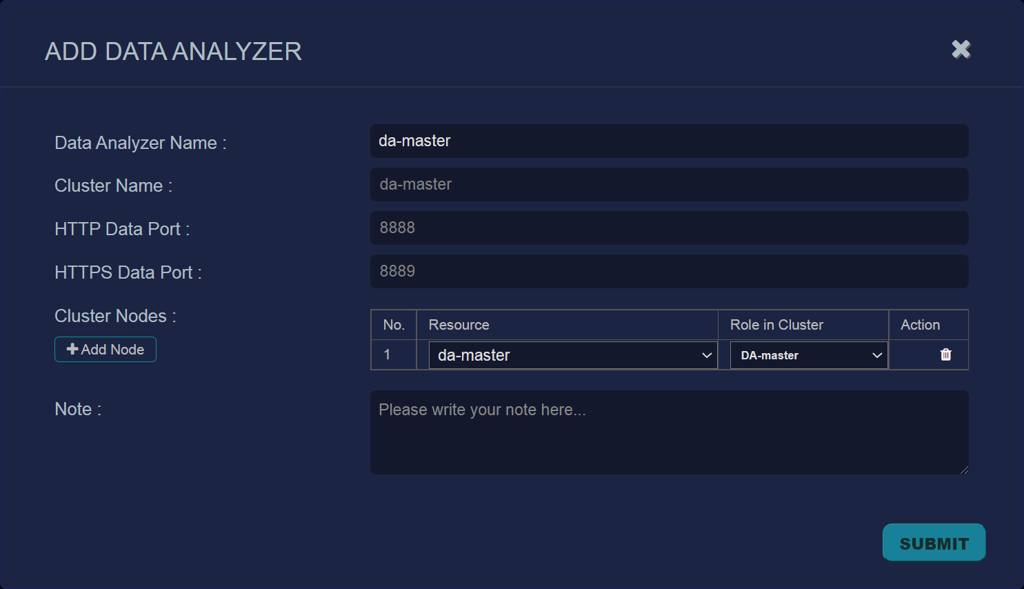
Supply the following information in the Add Data Analyzer dialog box:
-
Data Analyzer Name – da-master
-
Cluster Name – da-master
-
HTTP Data Port/DTTPS Data Port – Leave at default values.
-
Cluster Nodes – Click the Add Node button and use the Resource dropdown to select the da-master. Then, set the Role in Cluster dropdown to DA-Master and click Submit, as in the figure below.

-
-
Wait a few minutes, refresh the Data Analyzer Configuration page, and make sure the Node List column has updated from 0 Nodes to 1 Nodes with a green icon in the Status column.
Configuring Roles in a Cluster Deployment
To configure the Data Lake Master role:
- Open a console connection to the DLm VM.
- Log in. The default user/password is aella/changeme. You are immediately prompted to change the password.
- Change the password.
-
By default, the VM uses DHCP to obtain an IP address. You can use the show interface command to see the IP address. If you prefer to assign static IP information, use the following commands:
set interface management ip [IP address for your DP, including netmask]
set interface management gateway [IP address of your gateway]
set interface management dns [IP address of your DNS, or 8.8.8.8]
-
Assign a unique hostname to the VM with the set hostname command. For example:
set hostname dl-master
-
Reboot the VM with the reboot command.
-
Open a new console connection to the DLm VM if it is not still open and log in.
-
Assign the DL-master role to the VM with the following command:
set role DL-master
-
Configure the cluster name and size with the following commands:
set cluster_name dl-master
set cluster_size 1
-
Use the following command to verify that the ens224 interface is available:
show interface all
-
Set the cluster interface to ens224 with the following command:
set cluster_interface ens224
-
Use the set interface cluster ip command to specify the IP address and subnet mask of the VM's cluster interface (the interface on the second vNIC). For example:
set interface cluster ip 192.168.12.25/24
-
Use the show interface command to make sure the cluster interface is configured.
-
Use the set cm command to specify the IP address of the Data Lake's cluster interface (that is, the IP address you just assigned to the cluster interface. For example, using the IP address we just set:
set cm 192.168.12.25
-
Specify the one-time password (OTP) you received from Stellar Cyber with the following command:
set otp [OTP you received from Stellar Cyber -
Reset the VM with the following command:
reset
-
Confirm the reset. The image is downloaded (which can take a while, depending on your network) and installed.
-
Verify that everything is installed, ready, and running with the
show statuscommand. A screen similar to the following appears as it is installing:
If you change the hostname again after installation completes, you must run the reboot and reset commands from the VM command line.
When it finishes the status is similar to:
The installation of the Data Lake Master is complete. Next, configure the Data Analyzer.
To configure the Data Analyzer Master role:
You configure the Data Analyzer Master role by first assigning its role as a resource with its CLI. Then, once the DAm is up and running, you convert it to a Data Analyzer Master from within Stellar Cyber. Use the following procedure:
- Open a console connection to the DAm VM.
- Log in. The default user/password is aella/changeme. You are immediately prompted to change the password.
- Change the password.
-
By default, the VM uses DHCP to obtain an IP address. You can use the show interface command to see the IP address. If you prefer to assign static IP information, use the following commands:
set interface management ip [IP address for your DP, including netmask]
set interface management gateway [IP address of your gateway]
set interface management dns [IP address of your DNS, or 8.8.8.8]
-
Assign a unique hostname to the VM with the set hostname command. For example:
set hostname da-master
-
Reboot the VM with the reboot command.
-
Open a new console connection to the DAm VM if it is not still open and log in.
-
Use the following command to verify that the ens224 interface is available:
show interface all
-
Set the cluster interface to ens224 with the following command:
set cluster_interface ens224
-
Use the set interface cluster ip command to specify the IP address and subnet mask of the VM's cluster interface (the interface on the VM's second vNIC). For example:
set interface cluster ip 192.168.12.50/24
-
Use the show interface command to make sure the cluster interface is configured.
-
Assign the resource role to the VM with the following command:
set role resource
-
Use the set cm command to specify the IP address of the Data Lake's cluster interface. You configured this in the previous procedure. For example:
set cm 192.168.12.25
-
Reset the VM with the following command:
reset
-
Verify that everything is installed, ready, and running with the
show rolecommand. When the system reportsresource, the installation of the DAm VM is complete. Next, we need to convert it from its current resource role to a DA-Master from within the Stellar Cyber user interface. Use the following procedure.
If you change the hostname again after installation completes, you must run the reboot and reset commands from the VM command line.
To convert the DAm VM's role from "resource" to "DA-Master"
-
Once the show status command for the DLm reports System Ready and the show role command for the DAm reports Resource, log in to the DLm's graphical user interface with a web browser. For example:
https://<DLm Management IP Address>
The default credentials are a username of admin with a password of changeme.
-
Navigate to the System | Data Processor | Resources page and make sure you see a resource that is ready and available.
Do not edit the resource directly in the System | Data Processor | Resources page. Instead, use the System | Data Processor | Data Analyzer page to convert the resource's role, as described below.
-
Navigate to the System | Data Processor | Data Analyzer page and click the Create button to create a new DA cluster. Refer to Managing the Data Analyzer for details.
-
Supply the following information in the Add Data Analyzer dialog box:
-
Data Analyzer Name – da-master
-
Cluster Name – da-master
-
HTTP Data Port/DTTPS Data Port – Leave at default values.
-
Cluster Nodes – Click the Add Node button and use the Resource dropdown to select the da-master. Then, set the Role in Cluster dropdown to DA-Master and click Submit, as in the figure below.
-
-
Wait a few minutes, refresh the Data Analyzer Configuration page, and make sure the Node List column has updated from 0 Nodes to 1 Nodes with a green icon in the Status column.
Check Default Receiver Configuration and Sensor Profile
Stellar Cyber automatically configures a default receiver to be used as the destination of data collected by Photon sensors and other data sources. Before you add sensors to your new cluster, check the configuration of your default receiver in the System | Collection | Receivers page. Make sure that the Receiver Hostname is set to the IP address or hostname of the DA-Master (and not the DL-Master).
Once you have verified your receiver settings, check your Sensor Profile settings and make sure there is at least one sensor profile pointing to the receiver you just verified.
If you run into a situation where the show logforwarder command reports no output, it is likely that your receiver settings are incorrect. Double-check the Receiver Hostname and make sure it's set to the DA-Master's IP/hostname (cluster deployments) or DP's IP/hostname (AIO deployments).
Connecting the Security Data Sensor to the Data Lake Master (Integrated DP Deployments Only)
To connect the Security Data Sensor to the Data Lake Master:
- Open a console connection to the SDS VM.
- Log in to the SDS VM. The default user/password is aella/changeme. You are immediately prompted to change the password.
- Change the password.
-
Set the management addresses for the sensor with these commands:
set interface management ip [IP address for your sensor, including netmask]set interface management gateway [IP address of your gateway]set interface management dns [IP address of your DNS, or 8.8.8.8] -
Set the hostname to internalsds with the following command:
set hostname internalsds -
Specify the IP address of the Data Lake Master VM's management interface with the following command:
set cm [management IP address of the DLm] - Verify with the command
show cm. You should see the IP address of the DP listed as the CM Controller and the Status should be Established. - Verify the sensor status with the
show versioncommand. - Use the
show timecommand to see the default timezone setting. - Log out with the
quitcommand.
The sensor automatically contacts the DP to register itself.
Adding a Second Hard Disk to Data Lake VM
This procedure adds a second hard disk to the Data Lake VM to store Elasticsearch data. The disk must be at least 12TB. You create it in the datastore you created for this purpose in Configure Storage.
-
Open a client connection to the ESXi server. We are using the VMware Host Client in this example.
-
Click the Virtual Machines entry in the Navigator panel.
-
Right-click on the DLm VM in the Virtual Machines window and select Edit settings from the context menu that appears. The Edit settings screen appears.
-
Click the Virtual Hardware tab and click Add hard disk.
-
Choose the New standard hard disk option. A new Hard Disk entry appears in the Edit Settings dialog box.
-
Cascade open the Hard Disk entry in the Edit Settings dialog box and use the Location option to change the datastore to a location with sufficient free storage to host a 12 TB+ disk.
-
Set the size of the hard disk to 12 TB+. Note that you must specify a size that is less than the total amount of free space in the datastore.
- Open a console connection to the Data Lake Master VM.
- Log in using the credentials you set in the previous procedure.
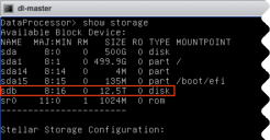
-
Verify that the new storage is available with the show storage command. The example below shows 12.5 TB available on sdb.
-
Use the add storage blk <bulk storage name> command to add the new disk for use by Elasticsearch. For example, using the sdb disk in our current example:

-
Type Y at the warning to format the selected disk.
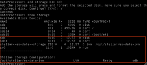
-
Use the show storage command to verify the disk is now available for use by Stellar Cyber. For example:
-
Log in to the DLm's graphical user interface with a web browser. For example:
https://<DLm Management IP Address>
-
Navigate to the System | Data Processor | Data Management | Advanced tab.
-
Click the Migrate to New Directory dropdown, select /es-data-lvm, and click the Start Migration button. This migrates saved Elasticsearch data from /esdata to /es-data-lvm.
-
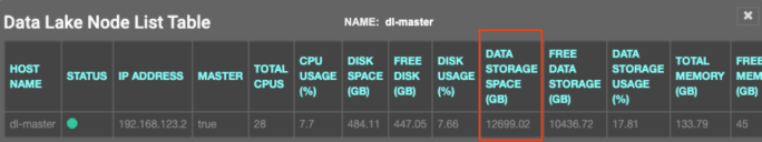
Once the data migration is complete, navigate to the System | Data Processor | Data Lake page and click the 1 items button in the Node List column.
-
Check the Data Storage Space column to verify that the expected capacity is available. For example:


Troubleshooting Tips
Use the following tips to troubleshoot common issues you may encounter while deploying the Data Processor:
-
Keep in mind that a DNS server setting is required for the DA and the DL. The procedures above indicate the required commands to specify a DNS server setting.
-
If deployment of the DP or Data Sensor VM appears stuck, there may not be a DHCP server available in the network. In cases like this, it can take 10-15 minutes for the Stellar Cyber VMs to come up. As a workaround, close the ESXi console connection and then re-open it again after 10 minutes. Note that after you configure a static IP for a VM, this delay will no longer occur at system startup.
Configuring CPU Scheduling Affinity
Use the procedures in this section to improve Stellar Cyber performance by configuring CPU Scheduling Affinity for the Data Lake Master and Data Analyzer Master VMs.
Security Data Sensors do not require configuration of CPU Scheduling Affinity.
About CPU Scheduling Affinity
An ESXi host has several NUMA nodes, each with multiple CPU cores assigned. For example, a sample configuration could consist of two NUMA nodes with each NUMA node associated with 44 different CPU cores for a total of 88 cores in the host device.
You can improve Stellar Cyber performance by configuring CPU Scheduling Affinity in ESXi with the following guidelines in mind:
-
Keep all vCPUs assigned to a VM on the same NUMA.
-
Configure CPU Scheduling Affinity so that different VMs on the same host do not need to compete for the same physical CPU core.
Reviewing CPU/NUMA Configuration
You can see the exact configuration of your host system's CPU cores and NUMAs with the esxcli hardware cpu list command from the host command line. For example:
[root@localhost:~] esxcli hardware cpu list | grep -E "CPU:|Node:"
CPU:0
Node: 0
CPU:1
Node: 0
CPU:2
Node: 0
CPU:3
Node: 0
CPU:4
Node: 0
CPU:5
Node: 0
(snip)
CPU:43
Node: 0
CPU:44
Node: 1
CPU:45
Node: 1
CPU:46
Node: 1
CPU:47
Node: 1
CPU:48
Node: 1
(snip)
CPU:86
Node: 1
CPU:87
Node: 1
In this example, you can see the following:
-
CPUs from 0-43 are on NUMA Node 0
-
CPUs from 44-87 are on NUMA Node 1
Planning CPU Scheduling Affinity Assignments
With the configuration we discovered in the previous section in mind, we can assign CPU Scheduling Affinity for the DL and DA so that they are on different NUMA nodes. Recall the CPU minimums from the Minimum System Requirements for Integrated DP and Production deployments:
-
Integrated DP Deployments:
-
DL – 28 CPU
-
DA – 28 CPU
-
-
Production Deployments:
-
DL – 40 CPU
-
DA – 44 CPU
-
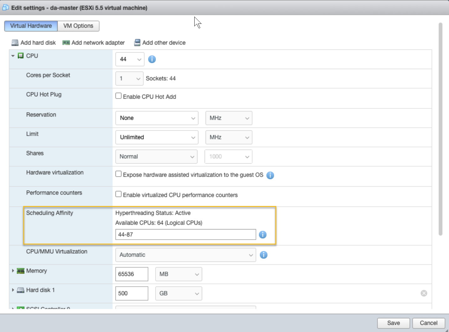
The figure below shows a sample configuration of CPU Scheduling Affinity that ensures the DL and DA both receive their minimum provisioning for the two different deployment types and are still on different NUMA nodes:
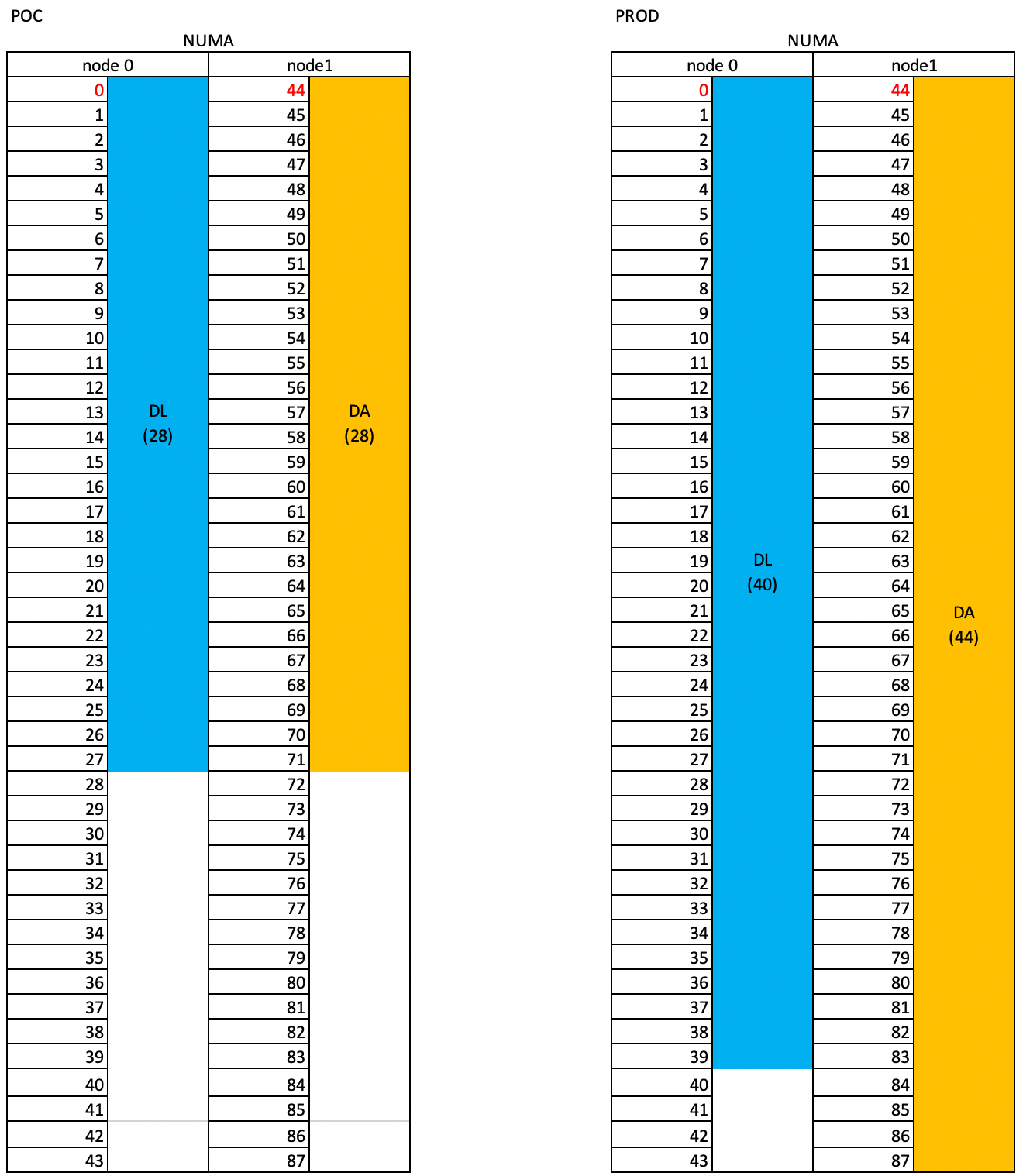
The figure shows the following sample configuration:
- Integrated DP Deployments:
-
DL – 28 CPUs configured on NUMA Node 0 from 0-27.
-
DA – 28 CPUs configured on NUMA Node 1 from 44-71.
-
-
Production Deployments:
-
DL – 40 CPUs configured on NUMA Node 0 from 0-39.
-
DA – 44 CPUs configured on NUMA Node 1 from 44-87.
-
Configuring CPU Scheduling Affinity in ESXi
Now that we know how we want to set up CPU Scheduling Affinity, we can go back to the ESXi client and make the necessary changes. Use the following procedure:
-
Open a client connection to the ESXi server. We are using the VMware Host Client in this example.
-
Click the Virtual Machines entry in the Navigator panel.
-
Right-click on the VM in the Virtual Machines window and select Edit settings from the context menu that appears. The Edit settings screen appears.
-
Click the Virtual Hardware tab and cascade open the CPU entry in the list.
-
Scroll down to the Scheduling Affinity entry and set the range to match the settings you planned in the previous section. The figures below show the settings for the DL and DA in a Production deployment:
Data Lake CPU Scheduling (Production)
Data Analyzer CPU Scheduling (Production)

-
Click Save to apply your changes.
-
Repeat this procedure for the other Data Processor VM (DL or DA, depending on which you configured first).